Sharp SF-1116 Manual de Serviço Página 55
- Página / 125
- Índice
- MARCADORES
- SERVICE MANUAL 1
- Contents 2
- AND MAIN CONTROL PWB 4
- REPLACEMENT 4
- [1] PRODUCT OUTLINE 5
- [2] PRODUCT SPECIFICATIONS 6
- 3. Supply parts 7
- 4. Optional specifications 9
- <Model name: SF-S54> 10
- Staple section 10
- (4) Exclusive-use desk 10
- [3] PRODUCT VIEWS 11
- EDGE ERASE 12
- Clutches and solenoids 13
- 5. Sensors and switches 15
- 6. Rollers, mirrors, etc 16
- 1. Unpacking 17
- 2. Installation 17
- 4. Charger cleaning 19
- 5. Developing unit setting 20
- 7. Accessory installation 21
- 8. Toner supply 21
- 9. Center shift adjustment 23
- 10. Label attachment 23
- [5] DESCRIPTIONS OF EACH 24
- 2. Developing section 25
- 3. Optical section 26
- • Brightness (F8.5) 27
- • Focus: (195mm ±1%) 27
- (Copy lamp 29
- (2) Dirt correction 30
- 4. Copy process 31
- 2) Process diagram 32
- OPC drum 36
- Blade Aluminum layer 36
- Residual toner 36
- 6) Process control function 37
- Process control 38
- Process control timing 38
- Drum marking 38
- Basic structure 38
- 5. TRANSPORT/FUSING SECTION 39
- 6. Fusing paper exit section 39
- 7. High voltage section 40
- [6] DISASSEMBLY AND ASSEMBLY 41
- 1-3. PS front roller ass’y 42
- 1-4. Separation roller 42
- 2. Transport unit 43
- 3. Fusing section 44
- 3-2. Heater lamp replacement 45
- 4. Optical system 46
- Optical adjustment plate 47
- Mirror base B 49
- Mirror base positioning plate 49
- No.2/3 mirror unit 49
- Horizontal scales 50
- Projections 50
- Inscribed 51
- 6) Lens wire replacement 52
- L drive pulley 53
- Lens unit 53
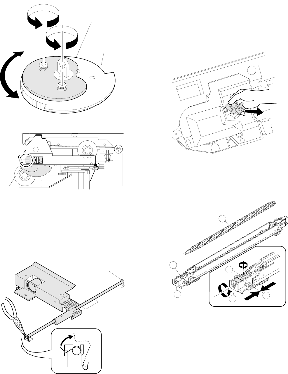
- Zooming cam drive gear 54
- Notch in the optical 55
- 17 1.0 56
- 6. Process section 57
- DV cover 60
- DV blade 60
- Stirring shaft B 61
- 31T gear 61
- 9-2. Power unit 62
- 9-3. Tray size detecting PWB 62
- 9-4. Main PWB unit 63
- 9-5. AC power PWB 63
- 10. Multi paper feed unit 64
- [7] ADJUSTMENTS 65
- 2. Optical system 66
- 2-2. Note for adjustments 67
- No.4/5 drive holder 68
- Shizuoka 69
- Lens value label 70
- 1scale: 1mm 71
- 10 20 90 100 110 72
- G. Vertical skew adjustment 74
- H. Horizontal skew adjustment 74
- Mirror base rail handle 75
- Loosen Loosen 75
- 1 scale = 1mm 75
- I. Center shift adjustment 76
- K. Copy lead edge adjustment 77
- 10 20 30 78
- Scale image 79
- (2) Drum sensitivity setting 80
- UKOG-0162FCZZ 81
- COPY DENSIty 82
- Copy density adjustment 83
- Not copied Slightly copied 84
- UKOG-0110FCZZ 85
- • Grid voltage adjustment 86
- • Grid voltage check 86
- [8] SIMULATION 87
- 4. List of simulations 88
- 5. Details of simulations 89
- 0.5s 0.5s 0.5s 90
- 0.5s 0.5s 91
- 4 Set the obtained values 100
- • B ... Manual feed 101
- 6. User simulation 102
- [9] SELF DIAGNOSTICS 104
- PLACEMENT 107
- 4. Set value recording sheet 109
- 5. Memory simulation list 110
- [11] MAINTENANCE 111
- [12] ELECTRICAL SECTION 112
- Power ON 113
- 2.Main circuit 114
- SC3041K12F 115
- 4 Internal block diagram 116
- DTA123YS 119
- 1 General 120
- 2 Operation 121
- M51953 BL 122
- (11) Operation panel 123
- COPYRIGHT 125
- 1997 BY SHARP CORPORATION 125
Manuais e produtos relacionados com Copiadoras Sharp SF-1116
 (2 páginas)
(144 páginas)
(10 páginas)
(286 páginas)
(16 páginas)
(14 páginas)
(97 páginas)
(47 páginas)
(20 páginas)
(2 páginas)
(4 páginas)
(2 páginas)
(200 páginas)
(36 páginas)
(108 páginas)
(4 páginas)
(2 páginas)
(8 páginas)
(2 páginas)
(144 páginas)
(10 páginas)
(286 páginas)
(16 páginas)
(14 páginas)
(97 páginas)
(47 páginas)
(20 páginas)
(2 páginas)
(4 páginas)
(2 páginas)
(200 páginas)
(36 páginas)
(108 páginas)
(4 páginas)
(2 páginas)
(8 páginas)
© 2020, manymanuals-pt.com. Todos os direitos reservados. | 0.036 s |
 Manymanuals.com
 Manymanuals.de
 Manymanuals.fr
 Manymanuals.it
 Manymanuals.pl
 Manymanuals.cz
 Manymanuals.es
 Manymanuals-pt.com
Comentários a estes Manuais