Sharp AR-810 Manual de Serviço
Consulte online ou descarregue Manual de Serviço para Impressora multifunções Sharp AR-810. Sharp AR-810 Service manual Manual do Utilizador
- Página / 342
- Índice
- MARCADORES

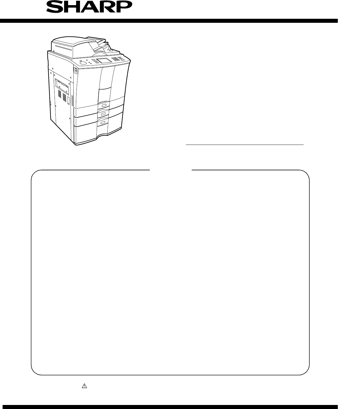
- SERVICE MANUAL 1
- CONTENTS 4
- 1. SPECIFICATIONS 6
- 1.1.2. Basic specifications 7
- C. Original 8
- D. Paper 8
- E. Paper feed 9
- F. Continuous copy 9
- G. Density adjustment 9
- H. Picture quality mode 9
- I. Magnification ratio 9
- J. Counter display 10
- K. Charger wire cleaning 11
- L. Special functions 11
- M. Edit functions 13
- N. Tab paper 13
- O. Digital edit function 13
- P. Operation panel 14
- Q. Environmental conditions 14
- R. Noises 15
- S. Complying standards 15
- T. Power source 15
- U. External view 15
- V. Packing 15
- W. Maintenance 16
- X. Automatic document feeder 16
- Y. Automatic duplex unit 16
- Z. Tandem LCF 17
- A. Image quality 17
- 1.2. Accessories 18
- 1.3. Options 18
- 1.4. Supplies 19
- 1.5. System List 20
- 2. 1. Sectional View 21
- 2. 2. Electric Parts Layout 25
- (B-3) PC board 27
- (B-4) Other parts 27
- Rear side 27
- [C] Laser unit 28
- [D] Transfer/Transport unit 28
- [E] Fuser unit 29
- [F] Copier unit 30
- (F-1) Motor/Fan 30
- (F-2) Clutch/Solenoid 31
- (F-3) Sensor/Switch 32
- (F-4) PC board 33
- (F-5) Other parts 34
- (1) Motors 36
- (2) Sensors and switches 38
- (4) PC boards 41
- (7) Transformer 42
- (5) Heaters and lamps 42
- (6) Solenoid 42
- (8) Others 43
- 2. 5. System Block Layout 46
- 2. 6. 1. Covers 47
- Left top cover 48
- Right top cover 48
- 2. 6. 2. PC boards 49
- 3. COPY PROCESS 51
- Surface potential (V) 52
- Type of originals 56
- Aluminum conductive base 57
- OPC layer 57
- 4. 2. 1. Warming-up 62
- Forward rotation 65
- Reverse rotation 65
- 4. 2. 4. Bypass copying 66
- 4. 2. 5. Interrupt copying 66
- 4. 3. Abnormality Detection 67
- 0.975sec 70
- 4. 4. 1. Power ON to ready 72
- Paper jam 75
- Drum reversed 75
- 5. CONTROL PANEL 76
- Fig. 5.2-1 79
- Fig. 5.2-2 79
- LCD PANEL 83
- 320 x 240 DOTS 83
- 5. 4. 2. LED display circuit 85
- MKEY board 87
- SKEY board 87
- LCD panel 87
- 6. SCANNING SECTION 88
- 6. 2. Construction 89
- 6. 3. 1. Scanner motor 91
- 6. 4. 1. General description 94
- 6. 4. 2. Exposure lamp 95
- Xenon lamp 96
- Xenon lamp 96
- 7497 7498 7499 7500 97
- Reflection type 98
- [A4 Series] 99
- [LT Series] 99
- Original 101
- Phototransistor 101
- Semi 102
- conductive 102
- 7. 2. 1. General description 103
- 7. 2. 2. Configuration 104
- 7. 3. 1. Features 105
- 0123456789 0123456789 106
- 7. 4. 1. Features 108
- 7. 5. Scanning Section 109
- 7. 6. Writing Section 109
- 8. LASER & OPTICAL UNIT 110
- >PS< 112
- 8. 3. Laser Diode 116
- Laser fan motor 117
- Connector 117
- 9. PAPER FEEDING SECTION 119
- 9. 3. Operation 122
- 9. 3. 3. Paper separation 123
- 9. 3. 4. General operation 124
- 1 2 3 4 5 6 7 128
- IN1 IN2 M(+) GND M(–) N.C. V 128
- Feed roller 130
- Separation roller 130
- Standby side empty sensor 142
- 10. PROCESS SECTION 144
- 10. 2. Functions 145
- 10. 4. 2. Operation 147
- J347-2 HVTVR 148
- J347-8 HVDVR 148
- J347-5 HVMVR 148
- 10. 5. 2. Construction 149
- 10. 5. 3. Control method 149
- Temperature/humidity sensor 154
- Surface potential sensor 154
- Duct out fan 155
- Exit fan 155
- 11. DRUM/CLEANER UNIT 156
- 11. 2. Functions 157
- Light emitting element 158
- Light sensing element 158
- 11. 4. 3. Outline of control 159
- 11. 4. 4. Construction 160
- Cleaner top cover 162
- Foot of screw 162
- E-ring Cam 164
- Separation finger 164
- Drum wheel 165
- Drum motor 165
- 12. DEVELOPER UNIT 166
- 12. 2. Functions 167
- 12. 3. Developer Unit Drive 169
- Developer unit drive 170
- 12. 4. Motor Drive Circuit 171
- 12. 4. 2. Developer motor 172
- 13. TRANSFER/TRANSPORT UNIT 187
- 13. 3. Functions 188
- Cam Lever 190
- 14. FUSER UNIT 197
- 14. 3. Functions 198
- 14. 4. 1. Configuration 200
- Photocoupler 201
- Thermistor 206
- Main CPU 206
- M/DC-HTR-340N 207
- 14. 5. 2. Control signals 208
- Upper separation finger 213
- Lower separation finger 213
- Entrance lower guide unit 214
- Cleaning roller (felt) 214
- Exit roller 214
- 2.0~2.5mm 215
- 15. EXIT/REVERSING UNIT 218
- E-ring Bearing 225
- 16. RADF (DOCUMENT FEEDER) 226
- 16. 2. Construction 227
- 16. 3. Drive System 228
- 16. 4. Signal Block Diagram 231
- 16. 5. Operations 232
- 16. 6. Jams 257
- 16. 7. Errors 262
- A4 series 264
- LT series 265
- 16. 9. Flow Chart 266
- (2) Rewriting of flash ROM 267
- (4) Initialization 269
- (5) Control for separation 270
- 16. 10. Timing Chart 282
- 16. 11. Circuits 287
- 16. 12. Input/Output Signals 293
- ADF front cover 298
- ADF rear cover 298
- Tray lift motor 302
- Read motor 302
- Tension spring 302
- Original length sensor 306
- Cover open/close switch 306
- Back cover 306
- Tray sensor 306
- RADF open/close switch 308
- Blue Orange Brown 308
- Scanning guide 308
- Large original exit guide 308
- Intermediate transport sensor 308
- Large original exit sensor 309
- Read sensor 309
- Upper transport guide 309
- Registration sensor 309
- Original width sensor 309
- Platen guide 310
- 17. POWER SUPPLY UNIT 317
- 17. 3. Output Channel 318
- 17. 4. Fuse 321
- 17. 6. Power Supply Sequence 324
- 18. PRINTED WIRING BOARDS 325
- (2) PWA-F-LGC-340 326
- (3) PWA-F-SLG-340 327
- (4) PWA-F-PLG-340 328
- (5) PWA-F-CCD2-340 329
- (6) PWA-F-LDR-340 330
- (7) PWA-F-SNS-340 330
- (8) PWA-F-MOT-340 330
- (9) PWA-F-MOT2-340 331
- (Japan only) 332
- Trademark Acknowledgments 342
Resumo do Conteúdo
CONTENTSParts marked with “ ” are important for maintaining the safety of the set. Be sure to replace these parts withspecified ones for maintaining t
AR-651/810 SPECIFICATIONS 1 - 5(2) Selected magnification ratioa. AB seriesb. LT SeriesNote: Figures indicate the selected magnification ratios (%).
AR-651/810 SCANNING SECTION 6 - 13(4) Original size is determined by the combination of the presence/absence of signals which are output ateach dete
AR-651/810 SCANNING SECTION 6 - 14The reflection type photosensor is comprised of an infrared light emitting diode and a phototransistor. Ituses the
AR-651/810 IMAGE PROCESSING 7 - 17. IMAGE PROCESSING7. 1. General DescriptionThe following diagram shows the process from scanning of the original
AR-651/810 IMAGE PROCESSING 7 - 27. 2. Image Processing Circuit7. 2. 1. General descriptionThe image of an original placed on the original glass i
AR-651/810 IMAGE PROCESSING 7 - 37. 2. 2. ConfigurationThe following diagram shows the image processing section of this copier.Configuration of ima
AR-651/810 IMAGE PROCESSING 7 - 47. 3. SLG Board (PWA-F-SLG-340)7. 3. 1. Features(1) The image processing ASIC on the SLG board is controlled by t
AR-651/810 IMAGE PROCESSING 7 - 50123456789 0123456789(b) FilteringThis function is enabled by a low-pass filter circuit and a high-pass filter circ
AR-651/810 IMAGE PROCESSING 7 - 6(2) Image memory editingThis function performs editing such as enlargement/reduction, mirror imaging, etc. using th
AR-651/810 IMAGE PROCESSING 7 - 77. 4. PLG Board (PWA-F-PLG-340)7. 4. 1. Features(1) The image processing ASIC on the PLG board is controlled by t
AR-651/810 IMAGE PROCESSING 7 - 87. 5. Scanning SectionLight reflected from original surface is directed to the CCD which performs the opto-electro
AR-651/810 SPECIFICATIONS 1 - 6K. Charger wire cleaningNote: The charger wire is cleaned.L. Special functionsCharger wire cleaning Automatic cleanin
AR-651/810 LASER & OPTICAL UNIT 8 - 18. LASER & OPTICAL UNIT8. 1. General DescriptionThe laser optical unit radiates the laser beam onto t
AR-651/810 LASER & OPTICAL UNIT 8 - 2fØ lens 1fØ lens 2Laser emission unit1st laser diodeFinite focus lens2nd laser drive PC board2nd laser diod
AR-651/810 LASER & OPTICAL UNIT 8 - 3[CAUTION]• Do not place reflective tools near the path of the laser beam.• Take off your watches, rings, br
AR-651/810 LASER & OPTICAL UNIT 8 - 4(2) Polygonal motor unitThis unit consists of the polygonal motor, polygonalmirror and polygonal mirror cov
AR-651/810 LASER & OPTICAL UNIT 8 - 5(3) fØ lenses 1 and 2These two lenses perform the following adjustment on the laser beams reflected by the
AR-651/810 LASER & OPTICAL UNIT 8 - 6(5) Laser drive boardThis control board has the following functions:a. APC control function (adjusts dispar
AR-651/810 LASER & OPTICAL UNIT 8 - 7Fig. 8.3-2 shows a block diagram of the semiconductive laser control circuit. The semiconductive lasermonit
AR-651/810 LASER & OPTICAL UNIT 8 - 8(2) Remove 2 screws and take off the optical unitfixing stay.8. 4. Disassembly and Replacement[A] Laser fa
AR-651/810 LASER & OPTICAL UNIT 8 - 9(3) Remove the laser fan motor.(4) Disconnect 3 connectors and pull out the laserunit.[C] Laser control P
AR-651/810 PAPER FEEDING SECTION 9 - 19. PAPER FEEDING SECTION9. 1. General DescriptionThe paper feeding system is for transporting paper set on th
AR-651/810 SPECIFICATIONS 1 - 7Sheet insertion mode Yes (following 2 modes)(1) White sheet insertion mode(2) Copy paper insertion modeWeekly timer Y
AR-651/810 PAPER FEEDING SECTION 9 - 2(1) Pickup rollerThese rollers draw paper off the stack from the bypass tray, cassette or tandem LCF and send i
AR-651/810 PAPER FEEDING SECTION 9 - 3(10)Tray-up sensorThis sensor detects the tray position when the paper lift plate of the cassette and tandem LC
AR-651/810 PAPER FEEDING SECTION 9 - 49. 3. Operation9. 3. 1. Operation of bypass pickup rollerWhen the bypass pickup solenoid is turned ON, the pl
AR-651/810 PAPER FEEDING SECTION 9 - 59. 3. 3. Paper separationThis model is equipped with a separation roller whichworks to prevent multiple paper
AR-651/810 PAPER FEEDING SECTION 9 - 69. 3. 4. General operation[A] From power ON to standby status(1) When the copier is turned ON, the tray-up mot
AR-651/810 PAPER FEEDING SECTION 9 - 7[E] Tandem LCF(E-1) From power ON to standby status(1) When the copier is turned ON, the power is supplied to s
AR-651/810 PAPER FEEDING SECTION 9 - 8(E-2) Standby status(1) Trays detect the paper as described above, and the copier goes into the standby status
AR-651/810 PAPER FEEDING SECTION 9 - 9b) Call for service(1) When the tandem LCF tray-up sensor is not turned ON even through a specified time has pa
AR-651/810 PAPER FEEDING SECTION 9 - 109. 4. Drive Circuit for Tray-up MotorCassette tray-up motor (MOT) : Driven by IC72 (tray-up motor 1) and IC36
AR-651/810 PAPER FEEDING SECTION 9 - 119. 5. Disassembly and Replacement[A] Feed unit(A-1) Pickup roller/Feed roller/Separation roller(1) Remove the
AR-651/810 SPECIFICATIONS 1 - 8M. Edit functionsN. Tab paperO. Digital edit functionContinuous paper copy YesEdge erase YesNote: The edge erase prio
AR-651/810 PAPER FEEDING SECTION 9 - 12(7) Remove 1 clip and take off the pickup roller.(8) Remove 3 screws and take off the guide.(9) Remove 1 clip
AR-651/810 PAPER FEEDING SECTION 9 - 13(2) Disconnect 1 connector, remove 1 screw andtake off the transport sensor.Note: Make sure to put on the spri
AR-651/810 PAPER FEEDING SECTION 9 - 14(A-3) Feed clutch/Transport clutch(1) Release the harness from the harness clamp.Then remove 1 screw and take
AR-651/810 PAPER FEEDING SECTION 9 - 15(5) Remove 4 screws (2 in the front and 2 in therear side) and take off the guide.Remove 2 E-rings (1 in the f
AR-651/810 PAPER FEEDING SECTION 9 - 16(2) Remove 1 E-ring, disconnect 1 connector andrelease the intermediate transport clutch.Note: 1. When install
AR-651/810 PAPER FEEDING SECTION 9 - 17(6) Remove 1 clip, disconnect 1 connector, take off1 harness band and release the bypass feedclutch.Bypass fee
AR-651/810 PAPER FEEDING SECTION 9 - 18(9) Remove 4 screws and take off the guide.(12)Remove 3 screws, release 4 latches and takeoff the bypass tray
AR-651/810 PAPER FEEDING SECTION 9 - 19(13)Remove 1 screw and take off the plate spring.(14)Remove 1 screw (as shown with the white arrow)from the ba
AR-651/810 PAPER FEEDING SECTION 9 - 20[D] Tray drive unit(1) Remove the rear cover and take off the powersupply unit.(2) Remove 4 screws and take of
AR-651/810 PAPER FEEDING SECTION 9 - 21[F] Feed drive unit(1) Remove the power supply unit.(2) Remove 3 screws and take off the power cableconnectin
AR-651/810 SPECIFICATIONS 1 - 9P. Operation panelQ. Environmental conditionsOperation keys Hard keyNote 1: The number of keys is 19 as follows:ENERG
AR-651/810 PAPER FEEDING SECTION 9 - 22[G] Tandem LCF(G-1) Feed side front guide(1) Remove 2 screws fixing the feed side front guide.(2) Lift the p
AR-651/810 PAPER FEEDING SECTION 9 - 23(G-3) Standby side front guide(1) Remove 1 screw fixing the standby side frontguide and move the guide toward
AR-651/810 PAPER FEEDING SECTION 9 - 24(G-5) Standby side paper mis-stacking detectionsensor(1) Remove 2 screws and release the sensorbracket.(2) Di
AR-651/810 PAPER FEEDING SECTION 9 - 25(G-7) End fence stop position sensor(1) Disconnect 1 connector, remove 1 screw andrelease the bracket.(2) Rel
AR-651/810 PROCESS SECTION 10 - 110. PROCESS SECTION10. 1. ConstructionThis chapter describes the image formation process related units, parts and
AR-651/810 PROCESS SECTION 10 - 210. 2. Functions(1) DrumThe drum is a cylindrical aluminum base which has thinly applied to it an organic photosen
AR-651/810 PROCESS SECTION 10 - 310. 3. Charger Wire Cleaner Operational Circuit(1) Role of the charger wire cleaner circuitThis circuit is for cle
AR-651/810 PROCESS SECTION 10 - 410. 4. High-voltage Transformer Output Control Circuit10. 4. 1. General description The high-voltage transformer
AR-651/810 PROCESS SECTION 10 - 5J347-2 HVTVRJ347-8 HVDVRJ347-5 HVMVRBC-RAMIC58IC56IC18IC27Gatearray D/AconverterTransferDeveloperMainMain CPU
AR-651/810 PROCESS SECTION 10 - 610. 5. Surface Potential Sensor10. 5. 1. General descriptionThe surface potential sensor detects the surface pote
AR-651/810 SPECIFICATIONS 1 - 10R. NoisesS. Complying standardsT. Power sourceU. External viewV. PackingWhen ready 45dB (A) or lessWhen continuous c
AR-651/810 PROCESS SECTION 10 - 7(2) Conrol during warming-upWhen the warming-up begins, the control is carried out following (1) at the previous pa
AR-651/810 PROCESS SECTION 10 - 8Terminal coverLatch10. 6. Disassembly and Replacement[A] Main charger(1) Open the front cover and take off the fr
AR-651/810 PROCESS SECTION 10 - 9SpringWirePadTerminalCharger wire[B] Wire cleaner drive unit(1) Remove the main charger and cleaner unit.(2) Disco
AR-651/810 PROCESS SECTION 10 - 1045A[D] Ozone filter(1) Remove 1 screw and pull out the ozone filterat the exit side.[C] Discharge lamp(1) Remove
AR-651/810 PROCESS SECTION 10 - 11(3) Disconnect 1 connector, remove 1 screw andtake off the surface potential sensor.[F] Temperature/humidity sens
AR-651/810 PROCESS SECTION 10 - 12[G] Exhaust duct(1) Take off the exit side upper cover and openthe exit cover.(2) Disconnect 3 connectors and rel
AR-651/810 DRUM/CLEANER UNIT 11 - 111. DRUM/CLEANER UNIT11. 1. ConstructionThis chapter describes about the drum and cleaner unit related units, p
AR-651/810 DRUM/CLEANER UNIT 11 - 211. 2. Functions(1) Drum cleaning bladeIt is pushed to the drum with a certain pressure by a weight and scrapes
AR-651/810 DRUM/CLEANER UNIT 11 - 311. 4. Image Quality Control11. 4. 1. General descriptionThis copier carries out the image quality control with
AR-651/810 DRUM/CLEANER UNIT 11 - 411. 4. 3. Outline of controlStart controlling (e.g. during the pre-running after the power has been turned ON)[1
AR-651/810 SPECIFICATIONS 1 - 11W. Maintenance(1) Periodic inspectionX. Automatic document feeder(1)FunctionsY. Automatic duplex unitAR-651 AR810Exe
AR-651/810 DRUM/CLEANER UNIT 11 - 511. 4. 4. Construction• Image quality sensor : Emitting of the light which corresponds to the light controlvolta
AR-651/810 DRUM/CLEANER UNIT 11 - 6Main chargerCleaner unit11. 5. Disassembly and Replacement[A] Cleaner unit(1) Open the front cover and take off
AR-651/810 DRUM/CLEANER UNIT 11 - 7Cleaner top coverFoot of screw(5) Remove 3 screws and take off the front sideflange.(6) Pull out the drum upward.
AR-651/810 DRUM/CLEANER UNIT 11 - 8Recovery bladeARecovery bladeCleaner flameDrum surfaceCleaning brushHolding shaftPlate[D] Recovery blade(1) Remo
AR-651/810 DRUM/CLEANER UNIT 11 - 9E-ring CamSeparation finger(2) Remove 1 E-ring and take off the cam.(3) Move the shaft of the separation finger t
AR-651/810 DRUM/CLEANER UNIT 11 - 10[H] Drum motor(1) Remove the rear cover and take off the SYSboard and hard disk with the bracket.(2) Remove 3 s
AR-651/810 DEVELOPER UNIT 12 - 112. DEVELOPER UNIT12. 1. ConstructionThis chapter describes about the following units related to the development p
AR-651/810 DEVELOPER UNIT 12 - 212. 2. Functions(1) Toner cartridge drive unitThe toner cartridge is filled with toner and supplies it to the devel
AR-651/810 DEVELOPER UNIT 12 - 3g. Scattered toner recovery rollerThis is a roller for trapping and recovering the toner scattered from the develope
AR-651/810 DEVELOPER UNIT 12 - 412. 3. Developer Unit DriveTransport sleeve gear(G23)Idle gear (G19)Idle gear(G30/16)[Front side]Scattered toner r
AR-651/810 SPECIFICATIONS 1 - 12Z. Tandem LCFStandard provision1.1.3. Image, image specificationsA. Image qualityKind Single paper feed (Right), sin
AR-651/810 DEVELOPER UNIT 12 - 5Motor shaftG10Idle gearG48P25Idle gearP25G25Copier rear side driveMixer-2G45Idle gearG24Idle gearG20Lower and upper
AR-651/810 DEVELOPER UNIT 12 - 612. 4. Motor Drive Circuit12. 4. 1. New toner supply motorThe new toner supply motor (brush motor) is a motor for
AR-651/810 DEVELOPER UNIT 12 - 712. 4. 2. Developer motor5.1VPhasecomparatorCurrentdetectioncircuitRotationcontrolRoterpositiondetectorExcitedphase
AR-651/810 DEVELOPER UNIT 12 - 8<Control signals>(1) DEVCK signal (LGC DEV-MOT: input)This signal is a reference clock signal for the develo
AR-651/810 DEVELOPER UNIT 12 - 912. 5. Auto-toner Sensor Circuit12. 5. 1. General description(1) Functions of auto-toner circuit• Detection of the
AR-651/810 DEVELOPER UNIT 12 - 1012. 5. 2. Operation of auto-toner sensor(1) Functions of the auto-toner sensora. Initializing function: When the c
AR-651/810 DEVELOPER UNIT 12 - 11When the toner density is low:Toner ratio to the carrier in the developer material decreased촞 Magnetic resistance d
AR-651/810 DEVELOPER UNIT 12 - 1212. 6. Disassembly and Replacement[A] Toner cartridge drive unit(A-1) Toner cartridge drive unit(1) Open the fron
AR-651/810 DEVELOPER UNIT 12 - 13[B] Toner recycle unit(B-1) Toner recycle unit(1) Remove the toner cartridge drive unit.(2) Remove 2 screws and ta
AR-651/810 DEVELOPER UNIT 12 - 14[E] Developer material(1) Remove the developer unit.(2) Remove 2 screws and take off the top cover.(3) Tilt the de
AR-651/810 SPECIFICATIONS 1 - 131.2. Accessories1.3. OptionsOperation manualDrumDrum coverOperation Manual pocketSpacer for original tray Rear edge
AR-651/810 DEVELOPER UNIT 12 - 15Note: When installing the top cover, insert the latchescompletely and be careful not to catch upthe urethane seal.
AR-651/810 DEVELOPER UNIT 12 - 16[H] Guide roller(1) Remove the developer unit.(H-1) Front side(2) Remove 2 screws and take off the bracket and3 ge
AR-651/810 DEVELOPER UNIT 12 - 17[I] Scattered toner recovery roller/Developersleeves (magnetic roller)(1) Remove 3 screws and take off the front s
AR-651/810 DEVELOPER UNIT 12 - 18(8) Remove 4 E-rings and take off 2 gears.(9) Take off the developer sleeve holders at boththe front and rear sides
AR-651/810 DEVELOPER UNIT 12 - 19[K] Mixer(1) Remove the auto toner sensor.(2) Remove 2 E-rings and take off 2 rear sidegears.(3) If necessary, rem
AR-651/810 DEVELOPER UNIT 12 - 20(4) Remove the gear and 1 E-ring and take off thefront side paddle bushing.(5) If necessary, replace the oil seal t
AR-651/810 DEVELOPER UNIT 12 - 21[M] Developer unit motor(1) Remove the rear cover.(2) Remove the SYS board and hard disk with thebracket.(3) Disco
AR-651/810 TRANSFER/TRANSPORT UNIT 13 - 113. TRANSFER/TRANSPORT UNIT13. 1. General DescriptionTransfer/Transport unit consists of the transfer bel
AR-651/810 TRANSFER/TRANSPORT UNIT 13 - 213. 3. Functions(1) Transfer belt unitThe transfer belt is coated with a high-precision flat rubber belt a
AR-651/810 TRANSFER/TRANSPORT UNIT 13 - 3(8) Belt transport unit lock/unlock mechanismThe belt transport unit is locked inside the copier. It is str
AR-651/810 SPECIFICATIONS 1 - 141.4. SuppliesSEC/SECL/(LAG)Note 1) Master/individual cartons are printed in 2 languages (English/French).European Su
AR-651/810 TRANSFER/TRANSPORT UNIT 13 - 413. 4. Disassembly and Replacement[A] Transfer belt unit(1) Open the front cover, turn the handle clockwi
AR-651/810 TRANSFER/TRANSPORT UNIT 13 - 5[B] Transfer belt(1) Remove the transfer belt unit.(2) Turn the transfer belt keeping/feeding section90 d
AR-651/810 TRANSFER/TRANSPORT UNIT 13 - 6[C] Brush(1) Remove the transfer belt keeping/feeding section.(2) Remove 1 screw and take off the plate sp
AR-651/810 TRANSFER/TRANSPORT UNIT 13 - 7[F] Transfer/Transport unit(1) Open the front cover, turn the lever clockwiseand pull out the transfer/tra
AR-651/810 TRANSFER/TRANSPORT UNIT 13 - 8(6) Change the A or B section to the right handand hold the C section with the left hand. Thenlift the tran
AR-651/810 TRANSFER/TRANSPORT UNIT 13 - 9[G] Transport detection sensor(1) Remove the transfer belt and fuser unit.(2) Disconnect 1 connector, remo
AR-651/810 TRANSFER/TRANSPORT UNIT 13 - 10[I] Transfer belt drive motor unit(1) Remove the rear cover and take off the flywheel.(2) Disconnect 1 co
AR-651/810 FUSER UNIT 14 - 114. FUSER UNIT14. 1. General DescriptionThe toner is fused on the paper separated from the photoconductive drum by app
AR-651/810 FUSER UNIT 14 - 214. 3. Functions(1) IH coil (IH: Induction heating)The IH coil is inside the fuser roller and applies the induction hea
AR-651/810 FUSER UNIT 14 - 3This sensor is for detecting that the trailing edge of the paper has reached the fuser unit exit sensor andalso for dete
GENERAL PRECAUTIONS REGARDING THE INSTALLATIONAND SERVICE FOR THE COPIER AR-651/810The installation and service should be done by a qualified service
AR-651/810 SPECIFICATIONS 1 - 151.5. System ListLCFAR-LC4Printer boardAR-P15Printer controllerAR-PK2AR-PK3FinisherAR-F11Staple cartridgeAR-SC3Staple
AR-651/810 FUSER UNIT 14 - 4NLCPULGCIH5V SW5V SW14. 4. Heater Control Circuit14. 4. 1. Configuration[Block diagram of fuser unit and IH control ci
AR-651/810 FUSER UNIT 14 - 5D1T1C1C3CPUTr2(IGBT)IGBTdriveC2Tr1IGBTdrive14. 4. 2. Heating principle of IH coilThe magnetic field is generated by app
AR-651/810 FUSER UNIT 14 - 614. 4. 3. IH control circuit interface The IH control circuit uses a photocoupler as an insulator against the secondary
AR-651/810 FUSER UNIT 14 - 714. 4. 4. IH control circuit abnormalitiesThe IH output is stopped when an abnormality occurs in the IH control circuit
AR-651/810 FUSER UNIT 14 - 814. 4. 5. Temperature detecting sectionTo keep the fuser roller at a certain temperature, the center thermistor and sid
AR-651/810 FUSER UNIT 14 - 9(5) Error detection during warming up (2) If the output voltage of either the center thermistor or side thermistor (
AR-651/810 FUSER UNIT 14 - 1014. 4. 6. Detection of open-circuited thermistorsA thermistor is a device which resistance decreases when it detects a
AR-651/810 FUSER UNIT 14 - 1114. 5. Fuser Motor Drive14. 5. 1. Outline of operation(1) The LGC transmits control signals for the fuser motor rotat
AR-651/810 FUSER UNIT 14 - 1214. 5. 2. Control signals(1) HTRCK signal (LGC → MOT:Input)This signal is a reference clock signal for the fuser motor
AR-651/810 FUSER UNIT 14 - 1314. 6. Disassembly and Replacement[A] IH control board(1) Open the front cover, turn the handle clockwiseand take off
AR-651/810 COMPONENT LAYOUT & FUNCTIONS 2 - 12. COMPONENT LAYOUT & FUNCTIONS2. 1. Sectional View[A] Front side view21345 678910 1112131415
AR-651/810 FUSER UNIT 14 - 14[B] Fuser unit(1) Remove 2 screws and open the cover forwardslowly.(2) Remove 4 screws and release the IH coil fuserha
AR-651/810 FUSER UNIT 14 - 15(4) Remove 2 E-rings and take off the web pushingroller.Cautions:1. Take up the cleaning web a little (3~5 rotations wi
AR-651/810 FUSER UNIT 14 - 16[D] IH coil(1) Remove the cleaning web unit.(2) Remove 2 screws and take off the fuser cover(front).(3) Remove 2 screws
AR-651/810 FUSER UNIT 14 - 17[E] Upper separation finger unit(1) Remove 2 screws and take off the crank plateand upper separation finger unit.(2) R
AR-651/810 FUSER UNIT 14 - 18[G] Cleaning roller (felt)(1) Remove 2 screws and open the entrance lowerguide unit.(2) Remove the cleaning roller (fe
AR-651/810 FUSER UNIT 14 - 19[I] Fuser roller(1) Loosen 2 pressure screws completely.(2) Remove 2 screws and take off the fuser unitcover (rear).Fu
AR-651/810 FUSER UNIT 14 - 20(6) Remove 1 E-ring and take off the gear.(7) Remove 2 screws and take off the bearing (rear).(8) Remove 1 C-ring (fron
AR-651/810 FUSER UNIT 14 - 21[K] Web detection sensor(1) Remove the fuser unit cover (front).(2) Remove 1 screw and take off the web detectionsenso
AR-651/810 EXIT/REVERSING UNIT 15 - 115. EXIT/REVERSING UNIT15. 1. General DescriptionThis copier conducts a paper reverse operation when printing
AR-651/810 EXIT/REVERSING UNIT 15 - 2(a) 3 sheets × 1 copy Single-sided printing operation (A4/LT)Step 1Step 2Step 3Step 4Step 6Step 7Step 8[1][2]
AR-651/810 COMPONENT LAYOUT & FUNCTIONS 2 - 21 Exposure lamp2 Reflector3 Mirror 14 Mirror 25 Mirror 36 Original glass7 Lens8 CCD driving PC boar
AR-651/810 EXIT/REVERSING UNIT 15 - 3(b) 5 sheets × 1 copy Duplex printing operation (A4/LT)Step 1Step 2Step 3Step 4Step 9Step 6Step 7Step 8[1][2]
AR-651/810 EXIT/REVERSING UNIT 15 - 4(c) 3 sheets × 1 copy Single-sided printing operation (A3/LD/B4/LG/A4-R/LT-R)Step 1Step 2Step 3Step 4Step 9St
AR-651/810 EXIT/REVERSING UNIT 15 - 5(d) 4 sheets × 1 copy Duplex printing operation (A3/LD/B4/LG/A4-R/LT-R)Step 1Step 2Step 3Step 4Step 9Step 6St
AR-651/810 EXIT/REVERSING UNIT 15 - 615. 3. Disassembly and Replacement[A] Exit/Reverse unit(1) Remove 6 screws and take off the exit sidecover.(2)
AR-651/810 EXIT/REVERSING UNIT 15 - 7[C] Reverse sensor(1) Disconnect 1 connector, remove 2 screws (1 forthe lower sensor) and take off the sensors.
AR-651/810 EXIT/REVERSING UNIT 15 - 8[F] O-ringWhen installing the receiving tray, add the O-rings(service parts) to the exit roller in order to imp
AR-651/810 RADF (DOCUMENT FEEDER) 16 - 1The Reversing Automatic Document Feeder (RADF) is a device that automatically feeds originals oneby one to t
AR-651/810 RADF (DOCUMENT FEEDER) 16 - 216. 2. ConstructionOriginal feeding trayJam access coverFeeding/transporting sectionLarge original receivin
AR-651/810 RADF (DOCUMENT FEEDER) 16 - 316. 3. Drive System(1) Feed motor rotating forward (seen in front)(2) Feed motor rotating in reverse (see
AR-651/810 RADF (DOCUMENT FEEDER) 16 - 4Intermediatetransport roller(3) Read motor rotating in reverse (seen in front)RearRead motorRead rollerFron
AR-651/810 COMPONENT LAYOUT & FUNCTIONS 2 - 3123465 14 181615717891019111213[B] Rear side view (Drive system)
AR-651/810 RADF (DOCUMENT FEEDER) 16 - 5(5) Tray lift motor rotating forward (seen in front)Tray lift motorTray lift motorTray lift motor rotatesco
AR-651/810 RADF (DOCUMENT FEEDER) 16 - 616. 4. Signal Block Diagram LLMTS-SNSRADF (Reversing automatic document reader)COP-SWDFOP-SWDFOPN-SNSAP-SN
AR-651/810 RADF (DOCUMENT FEEDER) 16 - 716. 5. Operations16. 5. 1. A4 single-sided feeding(Operational condition: A4 original/Reproduction ratio: 1
AR-651/810 RADF (DOCUMENT FEEDER) 16 - 8(4) Start of feedingThe feed motor starts to rotate in reverse. After the feed motor has finished accelerati
AR-651/810 RADF (DOCUMENT FEEDER) 16 - 9The SCN-STR turns OFF when the trailing edge of the original has passed the scanning section, andbefore the
AR-651/810 RADF (DOCUMENT FEEDER) 16 - 10The SCN-SCR turns OFF when the leading edge of the original has reached the scanning section.When the trail
AR-651/810 RADF (DOCUMENT FEEDER) 16 - 11When the original has proceeded a specified distance after the small original exit sensor had detectedthe t
AR-651/810 RADF (DOCUMENT FEEDER) 16 - 1216. 5. 2. A4 two-sided feeding(Operational condition: A4 original/Reproduction ratio: 100%)(1) Original set
AR-651/810 RADF (DOCUMENT FEEDER) 16 - 13The large original exit solenoid turns OFF when the large original exit motor stops rotating.(6) Start of
AR-651/810 RADF (DOCUMENT FEEDER) 16 - 14When the leading edge of the original has been transported to the intermediate transport section andcome to
AR-651/810 COMPONENT LAYOUT & FUNCTIONS 2 - 41 Scanner motor2 Drive pulley3 Drive belt4 Driven pulley5 Drum motor6 Developer unit motor7 Registr
AR-651/810 RADF (DOCUMENT FEEDER) 16 - 15The SCN-STR turns OFF when the trailing edge of the original has passed the scanning section. At thesame ti
AR-651/810 RADF (DOCUMENT FEEDER) 16 - 16(12) Start of 2nd original back side scanningScanning begins after receiving the original transport signal
AR-651/810 RADF (DOCUMENT FEEDER) 16 - 17The small original exit motor starts to rotate forward. Then it starts to slow down with a specified timede
AR-651/810 RADF (DOCUMENT FEEDER) 16 - 1816. 5. 3. A4 single-sided feeding(Operational condition: A3 original/Reproduction ratio: 100%)(1) Original
AR-651/810 RADF (DOCUMENT FEEDER) 16 - 19(5) Start of 1st original scanningScanning begins after receiving the original transport signal from the co
AR-651/810 RADF (DOCUMENT FEEDER) 16 - 20When the trailing edge of the original has passed the 4th roller then proceeded a specified distance, thela
AR-651/810 RADF (DOCUMENT FEEDER) 16 - 21When the trailing edge of the original has passed the 4th roller then proceeded a specified distance, thela
AR-651/810 RADF (DOCUMENT FEEDER) 16 - 2216. 5. 4. A3 two-sided feeding(Operational condition: A3 original/Reproduction ratio: 100%)(1) Original set
AR-651/810 RADF (DOCUMENT FEEDER) 16 - 23When the trailing edge of the original has passed the scanning section, the SCN-STR turns OFF andboth the r
AR-651/810 RADF (DOCUMENT FEEDER) 16 - 24When the leading edge of the original has been transported to the large original exit side and come the3rd
AR-651/810 COMPONENT LAYOUT & FUNCTIONS 2 - 5DVunitProcessunitReversing automatic document feeder unitScanner unitLaser unitTransfer/Transport u
AR-651/810 RADF (DOCUMENT FEEDER) 16 - 25(9) Reversing and discharging of 1st originalBoth the large original exit and read motors start to rotate f
AR-651/810 RADF (DOCUMENT FEEDER) 16 - 26(10) Start of 2nd original top side scanningScanning begins after receiving the original transport signal f
AR-651/810 RADF (DOCUMENT FEEDER) 16 - 27(11) Start of 2nd original back side registeringSame operation as 16.5.2.(6)(12) Start of 2nd original back
AR-651/810 RADF (DOCUMENT FEEDER) 16 - 2816. 5. 5. Single-sided feeding at mixed-original mode(Operational condition: A4-R and FOLIO originals/Repro
AR-651/810 RADF (DOCUMENT FEEDER) 16 - 29The large original exit motor starts to slow down when the trailing edge of the original has proceeded aspe
AR-651/810 RADF (DOCUMENT FEEDER) 16 - 30(7) Back side registering to set the top sideSame operation as 16.5.2.(6)(8) Start of top side feedingSame
AR-651/810 RADF (DOCUMENT FEEDER) 16 - 31The large original exit motor starts to slow down when the trailing edge of the original has proceeded aspe
AR-651/810 RADF (DOCUMENT FEEDER) 16 - 3216. 6. Jams16. 6. 1. Jams at feeding section(1) Original jammed not reaching the original length sensor• J
AR-651/810 RADF (DOCUMENT FEEDER) 16 - 33(3) Original jammed not reaching the read sensor• Jam detectionThis jam is detected during the time after a
AR-651/810 RADF (DOCUMENT FEEDER) 16 - 34(2) Original jammed at the large original exit sensor (while discharging)• Jam detectionThis jam is detected
AR-651/810 COMPONENT LAYOUT & FUNCTIONS 2 - 6[B] Scanner unit(B-1) Motor/Exposure lamp(B-2) Sensor/SwitchS1-3S1-4S2S1-2S1-5Rear sideEXPM31M1Rear
AR-651/810 RADF (DOCUMENT FEEDER) 16 - 35(3) Original jammed not reaching the small original reverse sensor (from the small original reverse side to
AR-651/810 RADF (DOCUMENT FEEDER) 16 - 36(3) Original jammed not reaching the small original exit sensor (from the small original reverse side)• Jam
AR-651/810 RADF (DOCUMENT FEEDER) 16 - 3716. 7. ErrorsErrors can be divided into the sensor adjustment error, EEPROM error and tray lift motor erro
AR-651/810 RADF (DOCUMENT FEEDER) 16 - 3816. 8. Original Size DetectionThe original position base code is transmitted to the copier during the time
AR-651/810 RADF (DOCUMENT FEEDER) 16 - 3916. 8. 2. Original size detection chartNot over160mm?NOYESTray guidewidthdetectedreceivingORG-IN(mm)~114~1
AR-651/810 RADF (DOCUMENT FEEDER) 16 - 40Not over160mm?NOYESTray guidewidthdetectedreceivingORG-IN(mm)~110~178~237~268268~~110110~Tray guidewidthdeci
AR-651/810 RADF (DOCUMENT FEEDER) 16 - 4116. 9. Flow Chart(1) Power ON → Start of communication lineYESNOAPower ONJig board installed?Program rewri
AR-651/810 RADF (DOCUMENT FEEDER) 16 - 42(2) Rewriting of flash ROMYESNOAFlash ROM rewriting completedNormal ROM installed on jig board?Flash ROM del
AR-651/810 RADF (DOCUMENT FEEDER) 16 - 43(3) Start of communication line → Operation monitoringYESNOBNOYESInitializationYESNO1NONO3Cover closed?Orig
AR-651/810 RADF (DOCUMENT FEEDER) 16 - 44(4) InitializationInitialization completedRead motor forward rotationSmall original exit motor forward rotat
AR-651/810 COMPONENT LAYOUT & FUNCTIONS 2 - 7(B-3) PC board(B-4) Other partsSLGINVCCDRear sideTHMO4DHLDHRRear side
AR-651/810 RADF (DOCUMENT FEEDER) 16 - 45(5) Control for separationYESNOAControl for Separation startedLifting tray upLifting tray downFeed motor fo
AR-651/810 RADF (DOCUMENT FEEDER) 16 - 46(6) Control for pre-feeding from registration rollerYESFeed motor reverse rotationYESRead motor forward rota
AR-651/810 RADF (DOCUMENT FEEDER) 16 - 47(7) Trailing edge control for pre-feedingYESFeed motor stoppedOriginal length data acquiredNext original de
AR-651/810 RADF (DOCUMENT FEEDER) 16 - 48(8) Control for next original detectionYESControl for next original detection completedNext original separat
AR-651/810 RADF (DOCUMENT FEEDER) 16 - 49(9) Leading edge control during scanningYESFeed motor reverse rotationLarge original exit motor reverse rot
AR-651/810 RADF (DOCUMENT FEEDER) 16 - 50YESLarge original exit motor startedLeading edge control during scanning completedNONODisengagement solenoid
AR-651/810 RADF (DOCUMENT FEEDER) 16 - 51(10)Trailing edge control during scanningTrailing edge control during scanning startedScanning start signal
AR-651/810 RADF (DOCUMENT FEEDER) 16 - 52YESYES2Trailing edge control for large original discharging startedTrailing edge control during scanning com
AR-651/810 RADF (DOCUMENT FEEDER) 16 - 53(11)Trailing edge control for large original dischargeYESAfter transporting the specified pulse, large orig
AR-651/810 RADF (DOCUMENT FEEDER) 16 - 54(12)Leading edge control during transportingYESSmall original exit solenoid ONLarge original exit motor reve
AR-651/810 COMPONENT LAYOUT & FUNCTIONS 2 - 8[C] Laser unit[D] Transfer/Transport unitRear sideCLT3CLT1CLT2S3S5S4DHTTHMO3FUSERear sideGLVM2LDR1L
AR-651/810 RADF (DOCUMENT FEEDER) 16 - 55(13)Trailing edge control during transportingYESLarge original exit motor stoppedTrailing edge control for
AR-651/810 RADF (DOCUMENT FEEDER) 16 - 56(14)Leading edge/trailing edge control for small original dischargingYESSmall original exit motor decelerate
AR-651/810 RADF (DOCUMENT FEEDER) 16 - 5716. 10. Timing Chart(a) Two sheets of A3 single-sided originalOFFONOFFONOFFONOFFONOFFONOFFONOFFONOFFONOFFO
AR-651/810 RADF (DOCUMENT FEEDER) 16 - 58(b) Two sheets of A3 two-sided original0 1000 2000 3000 4000 5000 6000 7000 (ms)OFFONOFFONOFFONOFFONOFFONOFF
AR-651/810 RADF (DOCUMENT FEEDER) 16 - 598000 9000 10000 11000 12000 (ms)OFFONOFFONOFFONOFFONOFFONOFFONOFFONOFFONOFFONOFFONOFFONOFFONOFFONOFFONUpwor
AR-651/810 RADF (DOCUMENT FEEDER) 16 - 60(c) Two sheets of A4 single-sided original0 1000 2000 3000 4000 5000 6000 7000 (ms)OFFONOFFONOFFONOFFONOFFON
AR-651/810 RADF (DOCUMENT FEEDER) 16 - 61(d) Two sheets of A4 two-sided original0 1000 2000 3000 4000 5000 6000 7000 (ms)OFFONOFFONOFFONOFFONOFFONOF
AR-651/810 RADF (DOCUMENT FEEDER) 16 - 6216. 11. Circuits(1) Input circuits for read sensor, large original exit sensor, small original reverse sens
AR-651/810 RADF (DOCUMENT FEEDER) 16 - 63(2) Irruptive current control circuitThis circuit controls the irruptive current flowing into the current r
AR-651/810 RADF (DOCUMENT FEEDER) 16 - 64(3) Drive circuit for read motorThis circuit controls the rotation/stoppage and the direction of rotation, e
AR-651/810 COMPONENT LAYOUT & FUNCTIONS 2 - 9[E] Fuser unitM3THMO2THMO1THM1THM2THM3IHCOILIHS7M30S6THM5Rear side
AR-651/810 RADF (DOCUMENT FEEDER) 16 - 65(5) Drive circuit for large original exit motor, small original exit motor and tray lift motorSince the lar
AR-651/810 RADF (DOCUMENT FEEDER) 16 - 66(7) Reset circuitThis circuit generates a CPU reset signal when the power is turned ON and the power voltage
AR-651/810 RADF (DOCUMENT FEEDER) 16 - 67This is a circuit to connect to COM with one of the four analog input signals. As following table shows,the
AR-651/810 RADF (DOCUMENT FEEDER) 16 - 6816. 12. Input/Output Signals(1) TXD/ACK/REQ signalsThis is an input circuit to communicate with the copier.
AR-651/810 RADF (DOCUMENT FEEDER) 16 - 69(2) RXD/SCN-STR/DF_ACK/DF_REQ signalsThis is an input circuit to communicate with the copier. “1” substitut
AR-651/810 RADF (DOCUMENT FEEDER) 16 - 70(3) Input circuits for each sensorRADF open/closesensorAPS operation sensorOriginal width sensor 1Original w
AR-651/810 RADF (DOCUMENT FEEDER) 16 - 71Small original reversesensorRead sensorLarge original exitsensorOriginal length sensorThese are the input c
AR-651/810 RADF (DOCUMENT FEEDER) 16 - 72Signal logicDFOPNS (RADF open/close sensor) RADF open RADF closeAPS (APS operation sensor) APS OFF APS ONCOP
AR-651/810 RADF (DOCUMENT FEEDER) 16 - 7316. 13. Disassembly and Replacement[A] RADF unit(1) Remove the rear cover and disconnect 1connector.(2) Re
AR-651/810 RADF (DOCUMENT FEEDER) 16 - 74(B-3) ADF left cover(1) Remove 2 screws and take off the ADF leftcover while moving it downward.(3) Remove
3. Main Service Parts for Safety• The breaker's, door switch's, fuse's, thermostat's, thermofuse's, thermistor's, etc. a
AR-651/810 COMPONENT LAYOUT & FUNCTIONS 2 - 10[F] Copier unit(F-1) Motor/FanM20M18M17M28M24M11M13M23M25M26M27M29M16M19M22M21M12M14M15M5M6M4M10M9
AR-651/810 RADF (DOCUMENT FEEDER) 16 - 75(D-2) Separation roller(1) Open the jam access cover.(2) Remove the pickup unit.(3) Remove 2 screws and tak
AR-651/810 RADF (DOCUMENT FEEDER) 16 - 76(6) Remove the clip and pull out the pulley, parallelpin and separation roller from the shaft.Pulley, Paral
AR-651/810 RADF (DOCUMENT FEEDER) 16 - 77(E-2) Tray lift motor(1) Remove the ADF rear cover.(2) Remove the ADF board with the bracket.(3) Remove 2 s
AR-651/810 RADF (DOCUMENT FEEDER) 16 - 78(E-4) Small original exit motor(1) Remove the ADF rear cover.(2) Remove the ADF board with the bracket.(3)
AR-651/810 RADF (DOCUMENT FEEDER) 16 - 79(F-2) Large original exit solenoid(1) Remove the ADF front cover while keepingthe jam access cover open.(2)
AR-651/810 RADF (DOCUMENT FEEDER) 16 - 80(5) Disconnect 1 connector and take off the liftingtray lower limit sensor.(3) Open the reverse guide, deta
AR-651/810 RADF (DOCUMENT FEEDER) 16 - 81(G-4) Cover open/close switch(1) Remove the ADF rear cover.(2) Remove 1 screw and take off the cover open/c
AR-651/810 RADF (DOCUMENT FEEDER) 16 - 82(G-8) Intermediate transport sensor(1) Open the platen sheet and remove 1 screwfixing the band.(2) Move the
AR-651/810 RADF (DOCUMENT FEEDER) 16 - 83(G-9) RADF open/close switch(1) Remove the ADF rear cover.(2) Disconnect 3 connectors.(3) Remove 1 screw an
AR-651/810 RADF (DOCUMENT FEEDER) 16 - 84(5) Remove 1 screw, disconnect 1 connector andtake off the large original exit sensor with thebracket.(6) R
AR-651/810 COMPONENT LAYOUT & FUNCTIONS 2 - 11(F-2) Clutch/SolenoidCLT4SOL2SOL1CLT10CLT8CLT6CLT5SOL3CLT7CLT11CLT9SOL4SOL5Rear side
AR-651/810 RADF (DOCUMENT FEEDER) 16 - 85[H] Platen guide(1) Remove 2 screws fixing the platen guide.(2) Move the platen guide toward the direction
AR-651/810 RADF (DOCUMENT FEEDER) 16 - 86[I] Mylar and mirror seal(I-1) Mirror seal for original length sensorRef.Ref.0 ~ 0.5 mm0 ~ 0.5 mmUpper gu
AR-651/810 RADF (DOCUMENT FEEDER) 16 - 87Ref.0 ~ 0.5 mmPlaten outside guide(I-2) Mylar for read sensorMylarAttach the mylarpassing through theguide
AR-651/810 RADF (DOCUMENT FEEDER) 16 - 88Ref.0 ~ 0.5 mm(I-3) Mirror seal for large original exit sensorLarge originalexit guideRef.Mirror sealAttac
AR-651/810 RADF (DOCUMENT FEEDER) 16 - 89Ref.Ref.0 ~ 0.5 mm(I-4) Mirror seal for small original reversal sensor Under transport guidefor small orig
AR-651/810 RADF (DOCUMENT FEEDER) 16 - 90Ref.1 ~ 1.5 mm(I-5) Mirror seal for read sensorPlaten guideMirror sealMirror sealReference hole:Attach the
AR-651/810 RADF (DOCUMENT FEEDER) 16 - 91Ref.0 ~ 1.0 mm(I-6) Mirror seal for large original exit sensorMirror sealReverse guidePositioning other th
AR-651/810 POWER SUPPLY UNIT 17 - 117. POWER SUPPLY UNIT17. 1. ConstructionThe power supply unit is comprised of the AC filter and insulation typ
AR-651/810 POWER SUPPLY UNIT 17 - 217. 3. Output ChannelThere are 4 output channels which do not work with the door switch.(1) 3.3V3.3VA : J407 5pi
AR-651/810 POWER SUPPLY UNIT 17 - 3(4) 24V24VF : J408 1pin, 2pinOutput to RADF24VG : J406 4pinOutput to LGC boardThere are 3 output channels which w
AR-651/810 COMPONENT LAYOUT & FUNCTIONS 2 - 12(F-3) Sensor/SwitchS20S15S14S28S25S26S29S12S10S11S27S13S19S24S23S21S36S30S43S22S34S32S35S33S40S38S
AR-651/810 POWER SUPPLY UNIT 17 - 4<<Output connector>>Not working with the door switchJ405 for SYS boardJ406 for LGC boardJ407 for PLG
AR-651/810 POWER SUPPLY UNIT 17 - 517. 4. FuseWhen the power supply secondary fuse is blown out, confirm that there is no abnormality with each par
AR-651/810 POWER SUPPLY UNIT 17 - 6Voltage Board/Unit Part Fuse type24VC LGC Registration motor F5: 4A (Semi time-lag)LCF unitIH fan motorCassette t
AR-651/810 POWER SUPPLY UNIT 17 - 717. 5. Configuration of Power Supply UnitF5F6F1F3F7F8F10F2Reg.Reg.24VA(LGC)24VB(LGC)24VC(LGC)36VA(LGC)36VB(LGC)2
AR-651/810 POWER SUPPLY UNIT 17 - 8ON OFF17. 6. Power Supply SequenceAC input+3.3V(MAIN)+5.1V(MAIN)PWR-DN+12V(MAIN)+24V(MAIN)+5.1V(DOOR)+24V(DOOR)+
AR-651/810 PRINTED WIRING BOARDS 18 - 118. PRINTED WIRING BOARDS(1) PWA-F-SYS-340
AR-651/810 PRINTED WIRING BOARDS 18 - 2(2) PWA-F-LGC-340
AR-651/810 PRINTED WIRING BOARDS 18 - 3(3) PWA-F-SLG-340
AR-651/810 PRINTED WIRING BOARDS 18 - 4(4) PWA-F-PLG-340
AR-651/810 PRINTED WIRING BOARDS 18 - 5(5) PWA-F-CCD2-340
AR-651/810 COMPONENT LAYOUT & FUNCTIONS 2 - 13(F-4) PC boardLGCHVTMOT2MOTSYSHDDRear side
AR-651/810 PRINTED WIRING BOARDS 18 - 6(6) PWA-F-LDR-340(7) PWA-F-SNS-340(8) PWA-F-MOT-340
AR-651/810 PRINTED WIRING BOARDS 18 - 7(9) PWA-F-MOT2-340(10) PBA-CONTROL (ADF CONTROL PC BOARD)
AR-651/810 UNPACKING AND INSTALLATION 19 - 119. UNPACKING AND INSTALLATIONWARNINGThe unpacking and set-up procedure shall be done by a qualified ser
AR-651/810 UNPACKING AND INSTALLATION 19 - 28-2) REMOVE9) REPLACE10) OPEN11) REMOVE12) REMOVE13) REMOVE14) INSTALL15) REMOVE(Japan only)1312311212
AR-651/810 UNPACKING AND INSTALLATION 19 - 316) ROTATE17) DISCONNECT18) REMOVE19) REMOVE20) REMOVE21) REMOVE22) REMOVE23) REMOVE121211212312122
AR-651/810 UNPACKING AND INSTALLATION 19 - 424) REMOVE25) REMOVE26) REMOVE27) REMOVE28) APPLY29) LOCK30) APPLY31) INSTALL12
AR-651/810 UNPACKING AND INSTALLATION 19 - 532) UNLOCK33) ROTATE34) APPLY35) ROTATE36) INSTALL37) INSTALL38) INSTALL39) INSTALL121212121
AR-651/810 UNPACKING AND INSTALLATION 19 - 640) REMOVE41) FILL42) INSTALL43) INSTALL44) INSTALL45) INSTALL46) INSTALL47) ROTATE1231221212
AR-651/810 UNPACKING AND INSTALLATION 19 - 748) INSTALL49) CONNECT50) ROTATE51) INSTALL52) INSTALL• When options are installed, be sure to fasten th
AR-651/810 UNPACKING AND INSTALLATION 19 - 856) PLUG IN57) INSTALL58) ADJUSTMENTAdjustment of the Auto-Toner Sensor(1) While pressing keys [0] and [
AR-651/810 COMPONENT LAYOUT & FUNCTIONS 2 - 14(F-5) Other partsS48S9S8PSTHM4ERSBRK1NF1Rear side
AR-651/810 UNPACKING AND INSTALLATION 19 - 961) INSTALL62) TURN ON63) ADJUSTMENTSetting the time(1) Press the PROGRAM key to enter the program menu.
All rights reserved.Printed.No part of this publication may be reproduced,stored in a retrieval system, or transmitted,in any form or by any means,ele
AR-651/810 COMPONENT LAYOUT & FUNCTIONS 2 - 15SSOLESSOLLSOLSMOTLMOTTLMOTFMOTDFLGRMOTTRYSDFOPSWREADSAPSLLMTSCOPSEMPSLOESSIZE3REGSSOESSSBSTRVRCOPS
AR-651/810 COMPONENT LAYOUT & FUNCTIONS 2 - 162. 3. Symbols and Functions of Various Components(1) MotorsSymbol Name Function RemarksM1 SCAN-MO
AR-651/810 COMPONENT LAYOUT & FUNCTIONS 2 - 17M22 ADU-FAN-MOT1 Cooling down the reverse section (F-1)Reverse section fan motor 1M23 ADU-FAN-MOT2
AR-651/810 COMPONENT LAYOUT & FUNCTIONS 2 - 18(2) Sensors and switchesS1-1 – APS 1-5 Original size detection (B-2)S1-5 Automatic original detect
AR-651/810 COMPONENT LAYOUT & FUNCTIONS 2 - 19Symbol Name Function RemarksS23 TR-BELT-SW 2 Transfer belt contact position (F-3)Transfer belt con
ICONTENTS1. SPECIFICATIONS1. 1. Specifications . . . . . . . . . . . . . . . . . . 1-11. 2. Accessories. . . . . . . . . . . . . . . . . . . 1-131. 3
AR-651/810 COMPONENT LAYOUT & FUNCTIONS 2 - 20S45 EMP-SNR-SS Tandem LCF paper position (F-3)Standby side empty sensor detection at the standby s
AR-651/810 COMPONENT LAYOUT & FUNCTIONS 2 - 21Symbol Name Function Remarks(3) Electromagnetic spring clutchesCLT1 TR-DRV-CLT Driving of the reve
AR-651/810 COMPONENT LAYOUT & FUNCTIONS 2 - 22SOL1 SFB-SOL Driving of the bypass pickup roller (F-2)Bypass pickup solenoidSOL2 GATE-SOL Switchin
AR-651/810 COMPONENT LAYOUT & FUNCTIONS 2 - 23INV INV-EXP Control of the exposure lamp (B-3)Lamp inverterHDD HDD Storing of the image data (F-
AR-651/810 COMPONENT LAYOUT & FUNCTIONS 2 - 242. 4. Symbols and Functions of RADF Various Components(1) MotorsRMOT RMOT ·Driving of the transpo
AR-651/810 COMPONENT LAYOUT & FUNCTIONS 2 - 25COPSW COV-OPN-SW Interrupts power to the DF motors Micro switchCover open/close switch when the to
AR-651/810 COMPONENT LAYOUT & FUNCTIONS 2 - 262. 5. System Block LayoutSerial-I/FADFFinisherLCFIPCM-CPUGateArrayPFCPWA-F-LGC-340SRAMFlashROMNVR
AR-651/810 COMPONENT LAYOUT & FUNCTIONS 2 - 272. 6. Disassembly and Replacement ofCovers and PC boards2. 6. 1. Covers[A] Front cover/Front side
AR-651/810 COMPONENT LAYOUT & FUNCTIONS 2 - 28[D] Rear cover(1) Loosen 1 screw (shown by a white arrow),remove 6 screws, release 2 hooks and tak
AR-651/810 COMPONENT LAYOUT & FUNCTIONS 2 - 292. 6. 2. PC boards[A] System control board (SYS board)/Hard disk/Logic board (LGC board)(1) Remo
II14. FUSER UNIT14. 1. General Description. . . . . . . . . . . . . 14-114. 2. Operation. . . . . . . . . . . . . . . . . . . . . 14-114. 3. Functions
AR-651/810 COMPONENT LAYOUT & FUNCTIONS 2 - 30(3) Disconnect 19 connectors to the LGC board.(4) Remove 6 screws and take off the bracketwith the
AR-651/810 COPY PROCESS 3 - 13. COPY PROCESS3. 1. General Description(1) Charging: Negatively charges the surface of theOPC drum.훹(2) Original exp
AR-651/810 COPY PROCESS 3 - 23. 2. Details of Copy Process(1) OPC drumThe OPC drum has two layers, an outer and an innerlayer. The outer layer is a
AR-651/810 COPY PROCESS 3 - 3CCD lightreceivingamountValue ofimage signalsto be outputLight255Dark 0Difference between"light " and "d
AR-651/810 COPY PROCESS 3 - 4(5) DevelopmentDevelopment is a process of making the electro-static latent images visible to the eye (visible im-ages)
AR-651/810 COPY PROCESS 3 - 5• Developer materialThe developer material is a mixture of toner andcarrier. The toner is charged to negative polarity
AR-651/810 COPY PROCESS 3 - 6 Additional ExplanationThe life of the toner cartridge (number of copies) varies depending on the following conditions.
AR-651/810 COPY PROCESS 3 - 7Combined use of transfer belt andseparation fingerTo prevent the copy paper from failing tobe separated during the oper
AR-651/810 COPY PROCESS 3 - 8(7) FusingFusing is a process of melting and fixing the toneron the paper.Method : The melting point of the toner (mai
AR-651/810 COPY PROCESS 3 - 9(9) DischargingDischarging is a process of eliminating any (–)charge remaining on the OPC drum before the nextcharging
AR-651/810 SPECIFICATIONS 1 - 11. SPECIFICATIONS1.1. Specifications1.1.1. SystemCopy system Indirect electronic photo system (Dry type)Body type Con
AR-651/810 COPY PROCESS 3 - 103. 3. Comparison of Copy Process to AR-650/800Process1. Photoconductive drum(1) Sensitivity(2) Surface potential2. Ch
AR-651/810 COPY PROCESS 3 - 11Process AR-650/800 AR-651/81012. Fusing(1) System Long-life heat roller system Same as AR-650/800· Fuser roller: · Fus
AR-651/810 GENERAL OPERATIONS 4 - 14. GENERAL OPERATIONS4. 1. Overview of OperationCopier operation Operation during warming-up, pre-running and s
AR-651/810 GENERAL OPERATIONS 4 - 24. 2. 2. Standby state (ready for copying)• Keys on control panel enabled• When no key is pressed for a certain
AR-651/810 GENERAL OPERATIONS 4 - 3(7) Paper discharging• Exit sensor detecting passing of paper trailing edge• Main charger, developer bias and dis
AR-651/810 GENERAL OPERATIONS 4 - 402253613651423190623613652503680220830260 8308901790128018301270178026032403330430260 404029802470Timing chart fo
AR-651/810 GENERAL OPERATIONS 4 - 54. 2. 4. Bypass copying(1) Paper inserted into bypass feed tray.• SFB feed sensor turned ON~ “READY FOR BYPASS F
AR-651/810 GENERAL OPERATIONS 4 - 64. 3. Abnormality DetectionWhen an abnormality occurs in the copier, a symbol corresponding to the type of the a
AR-651/810 GENERAL OPERATIONS 4 - 7• When power is turned ON or feed unit initializing is operated:↓Presence or absence of paper detectedTray motor
AR-651/810 GENERAL OPERATIONS 4 - 8A-2) Bypass misfeed ( )• When doing a bypass feeding:Bypass feed pickup solenoid turned ON↓Registration sensor
AR-651/810 SPECIFICATIONS 1 - 21.1.2. Basic specificationsA. Copy speed(1) Continuous copyNote 1: Specification for manual set document, single copy
AR-651/810 GENERAL OPERATIONS 4 - 9B-1) Misfeed in copier ( )• Paper leading edge jam detected by exit sensorRegistration motor turned ON↓Exit se
AR-651/810 GENERAL OPERATIONS 4 - 10• When a sheet of reversed paper is transported:Transport sensor 1 not detecting paper in a certain timing↓“Clea
AR-651/810 GENERAL OPERATIONS 4 - 114. 4. Flowchart4. 4. 1. Power ON to readyYESYESNOANONONOYESYES"E03"Main SW ONDC power supply ONRes
AR-651/810 GENERAL OPERATIONS 4 - 12YESYESYESYESNOYESNONONONONOANOYESYESYESNO NO NO"C41" "C44" "CA1""C26"YES
AR-651/810 GENERAL OPERATIONS 4 - 134. 4. 2. Automatic feed copyingYESNONOYESYESYESNONONO"CA1"B"E01"YES"CA2"Press [ST
AR-651/810 GENERAL OPERATIONS 4 - 14YESNOB"E02"Paper jam Isfuser unit exit sensor ON?Main charger OFFDischarge
AR-651/810 CONTROL PANEL 5 - 15. CONTROL PANEL5. 1. Control Panel and Display PanelThe display unit consists of key switches and touch-panel switc
AR-651/810 CONTROL PANEL 5 - 2No. Message1 WAIT WARMING UP2 READY(WARMINGUP)3 READY4 COPYING5 Saving energy- Press [START]6 Place next originalPress
AR-651/810 CONTROL PANEL 5 - 3No. MessageState of copier Note12 READY(SADDLE STITCHTRAY FULL)13 READY(SET CORRECTCASSETTE)14 READY (ADDINGTONER)15 R
AR-651/810 CONTROL PANEL 5 - 4Fig. 5.2-1Fig. 5.2-2CAKIHEJBFDEG
AR-651/810 SPECIFICATIONS 1 - 3C. OriginalD. Paper(1) SizeNote 1: Postcards can be used. (Reverse copy and duplex copy are inhibited.)Note 2: Name c
AR-651/810 CONTROL PANEL 5 - 55. 2. 2. Display in abnormal conditionNo. Message1 Add paper2 Add tonerPress [HELP]3 Set key copycounter4 Paper misfe
AR-651/810 CONTROL PANEL 5 - 6No. MessageAbnormal state and indication on display panel Solution15 Select the samesized Inserter sheetsas the origin
AR-651/810 CONTROL PANEL 5 - 75. 3. Relation between Copier State and Operator’s ActionOperation START CLEAR Digital CassetteINTERRUPTENERGY SAVERB
AR-651/810 CONTROL PANEL 5 - 85. 4. Operation5. 4. 1. Dot matrix LCD circuit(1) StructureThe DSP-LCD-320 is an STN blue mode transmissive type LCD
AR-651/810 CONTROL PANEL 5 - 9(4) Data transmission(3) LCD drive operationThe following describes the drive operation to display the message “READY”
AR-651/810 CONTROL PANEL 5 - 10LDON0"L""L" 17D7Q3IC8(7932)R3(COPY)5VLLED4G5. 4. 2. LED display circuit(1) Method of LED display
AR-651/810 CONTROL PANEL 5 - 115. 5. Disassembly and Replacement[A] Control panel unit(1) Open the front cover and take off the front sideright inn
AR-651/810 CONTROL PANEL 5 - 12(6) Remove 9 screws and take off the MKEY board.(7) Remove 8 screws and take off the SKEY board.(8) Remove 4 screws a
AR-651/810 SCANNING SECTION 6 - 1Exposure lamp Carriage-1 Drive pulley6. SCANNING SECTION6. 1. FunctionIn the scanning section of this copier, the
AR-651/810 SCANNING SECTION 6 - 26. 2. ConstructionThe construction and purpose of the scanning system are described in this section.(1) Original g
AR-651/810 SPECIFICATIONS 1 - 4E. Paper feedF. Continuous copyG. Density adjustmentH. Picture quality modeI. Magnification ratio(1) Reduction, enlar
AR-651/810 SCANNING SECTION 6 - 3(3) Carriage-2The carriage-2 consists of mirror-2, mirror-3, etc. and directs the reflected light from the mirror-1
AR-651/810 SCANNING SECTION 6 - 4Carriage-1Carriage wireScanner motor Pulleys for carriage-26. 3. Operation6. 3. 1. Scanner motor(a) Scanning orig
AR-651/810 SCANNING SECTION 6 - 56. 3. 2. Two-phase motor drive circuit (fixed-current type)The scanner motor is driven by the unipolar transistors
AR-651/810 SCANNING SECTION 6 - 6SCN-MOTPWA-F-SLG123456654321IC4IC9J8SCNEN-0SCNDIR-0SCNRSTSCNREF-0ASCNMD3-0SCNMD2-0SCNMD1-0SCNCLK-01234J9+36V+36VCir
AR-651/810 SCANNING SECTION 6 - 76. 4. Control for Exposure Lamp6. 4. 1. General descriptionControl circuit of the exposure lamp consists of the f
AR-651/810 SCANNING SECTION 6 - 86. 4. 2. Exposure lampExternal electrode type Xenon fluorescent lamp is used as an exposure lamp in this copier.(1
AR-651/810 SCANNING SECTION 6 - 96. 4. 3. Control circuit for exposure lampHCT00IC16HCT00IC16HCT00IC16P24+5V+5VSWEXPON–0APWA–F–SLG–340EXPON–0WDTOUT
AR-651/810 SCANNING SECTION 6 - 106. 5. CCD Control6. 5. 1. Opto-electronic conversionA CCD (charge-coupled device) is used to produce an electric
AR-651/810 SCANNING SECTION 6 - 116. 6. Automatic Original Size Detection CircuitThis circuit detects the size of original (standard sizes only) us
AR-651/810 SCANNING SECTION 6 - 12[A4 Series][LT Series]Fig.6.6-3 Sensor detection pointsST LTLGLDST–RLT–RAPS-5APS-4APS-2APS-3A5 B5 A4B4A3A5–RA4–RB5
Mais documentos para Impressora multifunções Sharp AR-810


Manuais e produtos relacionados com Impressora multifunções Sharp AR-810
 (52 páginas)
(148 páginas)
(120 páginas)
(52 páginas)
(148 páginas)
(120 páginas)
 (176 páginas) (184 páginas)
(47 páginas)
(176 páginas) (184 páginas)
(47 páginas)
 (12 páginas) (126 páginas)
(32 páginas)
(12 páginas) (126 páginas)
(32 páginas)
© 2020, manymanuals-pt.com. Todos os direitos reservados. | 0.020 s |
 Manymanuals.com
 Manymanuals.de
 Manymanuals.fr
 Manymanuals.it
 Manymanuals.pl
 Manymanuals.cz
 Manymanuals.es
 Manymanuals-pt.com
Comentários a estes Manuais