Sharp 21B-FX1 Especificações
Consulte online ou descarregue Especificações para TVs e monitores Sharp 21B-FX1. Sharp 21B-FX1 Specifications Manual do Utilizador
- Página / 230
- Índice
- RESOLUÇÃO DE PROBLEMAS
- MARCADORES

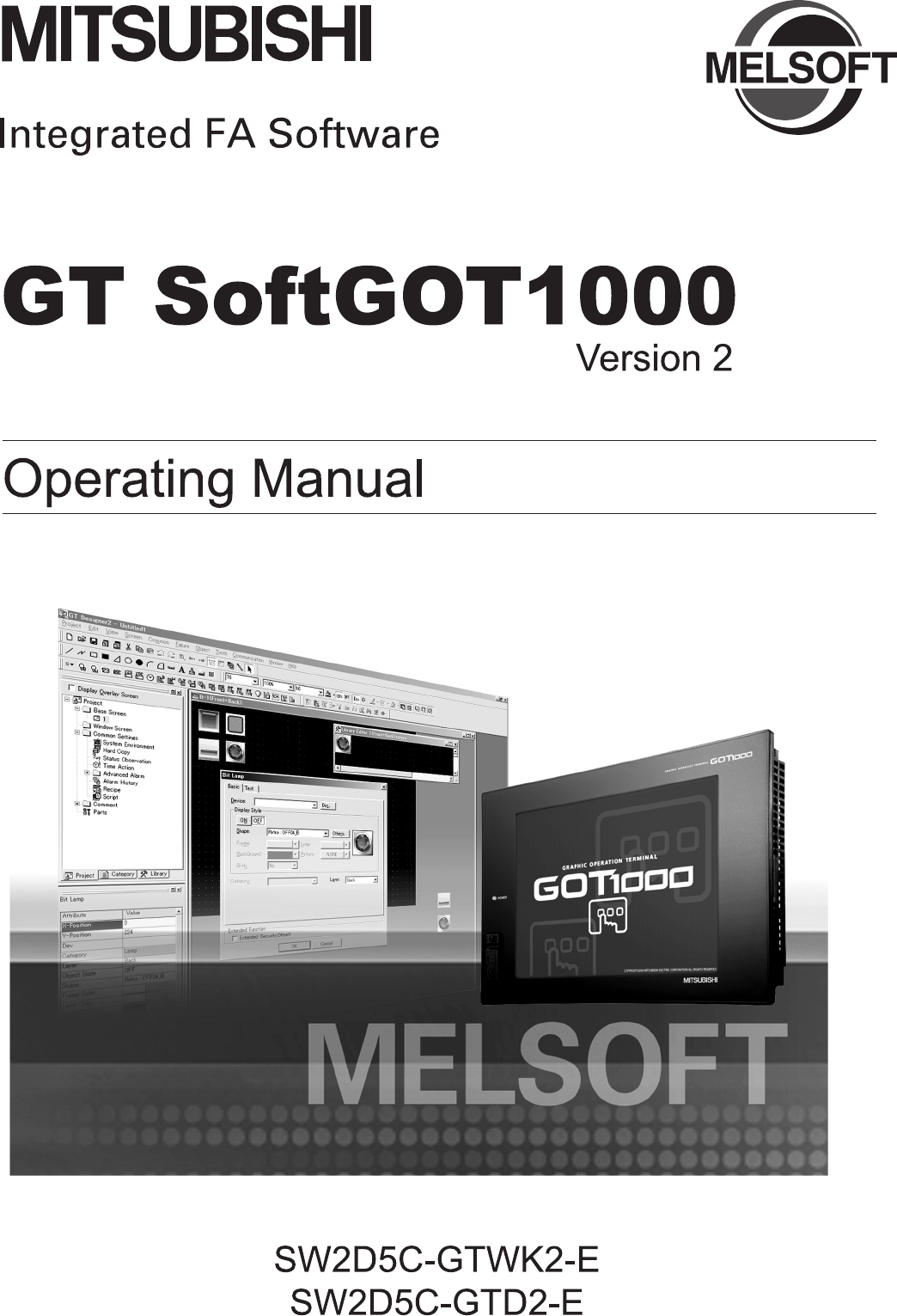
- SAFETY PRECAUTIONS 3
- REVISIONS 5
- Partial corrections 7
- Additions 7
- INTRODUCTION 8
- CONTENTS 8
- 6. FUNCTIONS 6 - 1 to 6 - 51 9
- INDEX index - 1 to index - 3 11
- ABOUT MANUALS 12
- Communication unit 14
- Option unit 14
- Software 15
- HOW TO READ THIS MANUAL 17
- 1. OVERVIEW 18
- 1.1 Features 19
- SoftGOT1000 20
- 2. SYSTEM CONFIGURATION 21
- 2.1 System Configuration 22
- 2.2 Operating Environment 24
- 2.2 Operating Environment 25
- 2.3 Connection conditions 26
- 2.3 Connection conditions 27
- 2.4 Connectable Modules 28
- 2.4 Connectable Modules 29
- 1 Ethernet module 30
- 2 Ethernet board/card 30
- 2.4.5 CNC 31
- 2.4.6 Robot controller 31
- 2.4.7 OMRON PLC 32
- 2.4.8 YASKAWA PLC 32
- 2.4.9 YOKOGAWA PLC 33
- 2.5 Connection Cable 34
- 2 Connecting to QSCPU 35
- USB cable 36
- 2.5 Connection Cable 37
- (3m)side) 38
- For A Series 45
- 2.5.5 Connecting to CNC 48
- 1 Connecting to CRnQ-700 49
- 2 Connecting to CRnD-700 49
- (a) Connection diagram 52
- • RS-232 cable 1) 52
- • RS-232 cable 2) 52
- • RS-232 cable 3) 52
- 3. SPECIFICATIONS 56
- 3.1 Specifications 57
- Utility operability 59
- 1 Numerical Display 60
- 2 Time display 60
- 3 GT Soft GOT1000 Versions 60
- 4 Virtual drive 60
- 6 Printer to output function 61
- 3.3 Precautions 62
- 4. SCREEN CONFIGURATION 66
- 4.1.2 Basic operation 67
- 4.2 Menu Bar 68
- 6. FUNCTIONS 69
- 4.4 Help 69
- 4.3 Tool bar 70
- 1 Operating method 71
- GOT900 series 72
- 5. OPERATING METHOD 73
- 5.2 Communication Setup 74
- (c) Communication setup 87
- 5.2 Communication Setup 100
- (b) Sequence program 102
- 6 When using MELDAS C6/C64 109
- (b) Communication setup 113
- Manual for CRnD-700 115
- \>Ping 192. 168. 0. 19 116
- \>Ping 192. 168. 0. 19 116
- 5.2.4 Setting on GT Designer2 118
- 1 Serial connection 121
- 2 Ethernet connection 121
- 1 Ethernet connection 124
- 5.3 Environment Setup 126
- 5.3 Environment Setup 127
- 2 Auxiliary Setup tab 128
- 5.4 Starting Monitoring 130
- 5.5 Opening the Project 131
- [Tool bar] 133
- Select either method 134
- 5.9 Automatic Startup 135
- 6. FUNCTIONS 136
- 6.2.1 Printing 137
- 6.2 Print 138
- 6.2.3 Performing page setup 139
- 6.2.4 Performing print setup 139
- 6.3 Property 140
- 6.4 Resource Data 141
- 6.5.1 Mail function overview 143
- 6.5 Mail Function 144
- 1 Mail setup 146
- GT SoftGOT1000 TEST MAIL 148
- This is a test message 148
- 2 Mail Condition 149
- 6.5.4 Sending e-mail 150
- 6.5.4 Sending e-mail 151
- 6.5.5 Mail history 152
- 6.6 Keyboard Input 153
- 6.6.4 Precautions 155
- 6.7.1 Full screen mode types 156
- 6.7.2 Setting method 158
- 6.7 Full Screen Mode 159
- 6.7.2 Setting method 159
- 6.7.3 Precautions 160
- 6.8.2 Precautions 161
- 6.9.1 Startup procedure 162
- 6.9.1 Startup procedure 163
- 6.9.2 Precautions for use 164
- 6.10.1 Window movement types 165
- 6.10.2 Setting method 166
- 6.11 System Alarm 167
- 6.12 Script Error 168
- 6.13 Object Script Error 169
- 6.14 Application Start-up 170
- 6.14.1 Setting method 171
- 6.14 Application Start-up 172
- 6.14.1 Setting method 172
- (2) Auxiliary Setup tab 173
- 2 Referring to history data 175
- 6.14.3 Precautions 176
- 6.15 Close Menu 177
- 6.16.1 Setting method 179
- 6.16.1 Setting method 180
- 2 Referencing history data 184
- 6.17.1 Setting method 185
- 6.18.1 Setting method 185
- 6.19 Exit Key 186
- 7. INTERNAL DEVICE INTERFACE 187
- FUNCTION 187
- 7.4 Sample Program 197
- Write value input area (GD) 198
- Write value input area (GS) 198
- Monitor execution status 198
- 8. TROUBLESHOOTING 200
- (Continued to next page) 201
- 8.1 Error Message 203
- 8.6.1 GOT error code list 208
- *1 215
- 1 GDev_OpenMapping function 221
- APPENDICES 222
- SoftGOT2) 223
- SoftGOT1000 Version Update 224
- SH(NA)-080602ENG-J 228
Resumo do Conteúdo
A - 86.4 Resource Data 6 - 66.5 Mail Function 6 - 86.5.1 Mail function overview ...
5 - 285.2 Communication Setup5.2.3 How to Set Up the Ethernet Connection4 When using Ethernet module (A series)The setting items and precautions a
5.2 Communication Setup5.2.3 How to Set Up the Ethernet Connection5 - 291OVERVIEW2SYSTEM CONFIGURATION3SPECIFICATIONS4SCREEN CONFIGURATION5OPERATI
5 - 305.2 Communication Setup5.2.3 How to Set Up the Ethernet Connection(b) Sequence programIP address of Ethernet module(192.168.0.2)Initial requ
5.2 Communication Setup5.2.3 How to Set Up the Ethernet Connection5 - 311OVERVIEW2SYSTEM CONFIGURATION3SPECIFICATIONS4SCREEN CONFIGURATION5OPERATI
5 - 325.2 Communication Setup5.2.3 How to Set Up the Ethernet Connection(7) Settings with GT Designer2 and GT SoftGOT1000(a) Ethernet settingMake
5.2 Communication Setup5.2.3 How to Set Up the Ethernet Connection5 - 331OVERVIEW2SYSTEM CONFIGURATION3SPECIFICATIONS4SCREEN CONFIGURATION5OPERATI
5 - 345.2 Communication Setup5.2.3 How to Set Up the Ethernet Connection(3) IP address setting (Setting with remote monitor tool): Required :
5.2 Communication Setup5.2.3 How to Set Up the Ethernet Connection5 - 351OVERVIEW2SYSTEM CONFIGURATION3SPECIFICATIONS4SCREEN CONFIGURATION5OPERATI
5 - 365.2 Communication Setup5.2.3 How to Set Up the Ethernet Connection(6) Settings on GT Designer2 and GT SoftGOT1000(a) Ethernet settingSet the
5.2 Communication Setup5.2.3 How to Set Up the Ethernet Connection5 - 371OVERVIEW2SYSTEM CONFIGURATION3SPECIFICATIONS4SCREEN CONFIGURATION5OPERATI
A - 97.2 Accessible Devices 7 - 17.3 Internal Device Interface Function 7 - 27.3.1 GDev_OpenMapping (Opening and mapping the internal device shared me
5 - 385.2 Communication Setup5.2.3 How to Set Up the Ethernet Connection(3) Network parameter settingSet the network parameters by peripheral devi
5.2 Communication Setup5.2.3 How to Set Up the Ethernet Connection5 - 391OVERVIEW2SYSTEM CONFIGURATION3SPECIFICATIONS4SCREEN CONFIGURATION5OPERATI
5 - 405.2 Communication Setup5.2.3 How to Set Up the Ethernet Connection(5) Setting on the personal computerSet the IP address.(6) Communications
5.2 Communication Setup5.2.3 How to Set Up the Ethernet Connection5 - 411OVERVIEW2SYSTEM CONFIGURATION3SPECIFICATIONS4SCREEN CONFIGURATION5OPERATI
5 - 425.2 Communication Setup5.2.3 How to Set Up the Ethernet Connection7 When using robot controller (CRnD-700)For communications between GT Soft
5.2 Communication Setup5.2.3 How to Set Up the Ethernet Connection5 - 431OVERVIEW2SYSTEM CONFIGURATION3SPECIFICATIONS4SCREEN CONFIGURATION5OPERATI
5 - 445.2 Communication Setup5.2.3 How to Set Up the Ethernet Connection(4) Setting on personal computerSet the IP address.(5) Communication check
5.2 Communication Setup5.2.3 How to Set Up the Ethernet Connection5 - 451OVERVIEW2SYSTEM CONFIGURATION3SPECIFICATIONS4SCREEN CONFIGURATION5OPERATI
5 - 465.2 Communication Setup5.2.4 Setting on GT Designer25.2.4 Setting on GT Designer2(1) Ethernet setting method(a) Operation procedureWhen eith
5.2 Communication Setup5.2.4 Setting on GT Designer25 - 471OVERVIEW2SYSTEM CONFIGURATION3SPECIFICATIONS4SCREEN CONFIGURATION5OPERATING METHOD6FUNC
A - 10ABOUT MANUALSThe following manuals are also related to this product.In necessary, order them by quoting the details in the tables below.*1 The
5 - 485.2 Communication Setup5.2.5 How to Set Up the OMRON PLC Connection5.2.5 How to Set Up the OMRON PLC ConnectionThe setting method when conne
5.2 Communication Setup5.2.6 How to Set Up the YASKAWA PLC Connection5 - 491OVERVIEW2SYSTEM CONFIGURATION3SPECIFICATIONS4SCREEN CONFIGURATION5OPER
5 - 505.2 Communication Setup5.2.6 How to Set Up the YASKAWA PLC Connection(1) Before setting(a) Communication precautions • Only communications w
5.2 Communication Setup5.2.6 How to Set Up the YASKAWA PLC Connection5 - 511OVERVIEW2SYSTEM CONFIGURATION3SPECIFICATIONS4SCREEN CONFIGURATION5OPER
5 - 525.2 Communication Setup5.2.7 How to Set Up the YOKOGAWA PLC Connection5.2.7 How to Set Up the YOKOGAWA PLC Connection1 Ethernet connectionTh
5.2 Communication Setup5.2.7 How to Set Up the YOKOGAWA PLC Connection5 - 531OVERVIEW2SYSTEM CONFIGURATION3SPECIFICATIONS4SCREEN CONFIGURATION5OPE
5 - 545.3 Environment Setup5.3.1 Environment setup dialog box5.3 Environment SetupIn Environment Setup, set the resolution, etc. of GT SoftGOT1000
5.3 Environment Setup5.3.1 Environment setup dialog box5 - 551OVERVIEW2SYSTEM CONFIGURATION3SPECIFICATIONS4SCREEN CONFIGURATION5OPERATING METHOD6F
5 - 565.3 Environment Setup5.3.1 Environment setup dialog box2 Auxiliary Setup tab(Continued to next page)Item DescriptionWindow Move MethodSelect
5.3 Environment Setup5.3.1 Environment setup dialog box5 - 571OVERVIEW2SYSTEM CONFIGURATION3SPECIFICATIONS4SCREEN CONFIGURATION5OPERATING METHOD6F
A - 11ABBREVIATIONS AND GENERIC TERMSAbbreviations and generic terms used in this manual are as follows: GOTAbbreviations and generic terms Descriptio
5 - 585.4 Starting Monitoring 5.4 Starting MonitoringThis section describes how to perform monitoring with the project data monitored previously.1
5.5 Opening the Project5 - 591OVERVIEW2SYSTEM CONFIGURATION3SPECIFICATIONS4SCREEN CONFIGURATION5OPERATING METHOD6FUNCTIONS7INTERNAL DEVICE INTERFACE
5 - 605.5 Opening the Project 3 Confirmation dialog box is displayed. (The dialogue box is not displayed if GT SoftGOT1000 is already in online mo
5.6 Monitoring Operation5 - 611OVERVIEW2SYSTEM CONFIGURATION3SPECIFICATIONS4SCREEN CONFIGURATION5OPERATING METHOD6FUNCTIONS7INTERNAL DEVICE INTERFAC
5 - 625.8 Exiting from GT SoftGOT1000 5.8 Exiting from GT SoftGOT1000This section describes how to exit from GT SoftGOT1000.1 Perform either of th
5.9 Automatic Startup5 - 631OVERVIEW2SYSTEM CONFIGURATION3SPECIFICATIONS4SCREEN CONFIGURATION5OPERATING METHOD6FUNCTIONS7INTERNAL DEVICE INTERFACE F
6 - 16.1 Snap Shot 6. FUNCTIONS6.1 Snap ShotThe screen image being monitored is saved into BMP or JPG format file.1 Perform the following operatio
6.2 Print6.2.1 Printing6 - 21OVERVIEW2SYSTEM CONFIGURATION3SPECIFICATIONS4SCREEN CONFIGURATION5OPERATING METHOD6FUNCTIONS7INTERNAL DEVICE INTERFAC
6 - 36.2 Print6.2.2 Performing print preview6.2.2 Performing print preview1 Perform the following operation.• Select [Project] [Print Preview] f
6.2 Print6.2.3 Performing page setup6 - 41OVERVIEW2SYSTEM CONFIGURATION3SPECIFICATIONS4SCREEN CONFIGURATION5OPERATING METHOD6FUNCTIONS7INTERNAL DE
A - 12 Communication unit*1 A9GT-QJ71LP23 + GT15-75IF900 set*2 A9GT-QJ71BR13 + GT15-75IF900 set*3 A8GT-J61BT13 + GT15-75IF900 set Option unit*1 GT15-C
6 - 56.3 Property 6.3 PropertyThe project title, project ID and data size of project data being monitored are displayed.1 Perform the following op
6.4 Resource Data6 - 61OVERVIEW2SYSTEM CONFIGURATION3SPECIFICATIONS4SCREEN CONFIGURATION5OPERATING METHOD6FUNCTIONS7INTERNAL DEVICE INTERFACE FUNCTI
6 - 76.4 Resource Data Resource dataData cannot be updated while being referenced. (The data is held.)(The held data is reflected when the print d
6.5 Mail Function6.5.1 Mail function overview6 - 81OVERVIEW2SYSTEM CONFIGURATION3SPECIFICATIONS4SCREEN CONFIGURATION5OPERATING METHOD6FUNCTIONS7IN
6 - 96.5 Mail Function6.5.1 Mail function overview(2) Using system alarmsAn error definition is sent at system alarm occurrence.The system alarm t
6.5 Mail Function6.5.2 Operation flow when using the mail function6 - 101OVERVIEW2SYSTEM CONFIGURATION3SPECIFICATIONS4SCREEN CONFIGURATION5OPERATI
6 - 116.5 Mail Function6.5.3 How to set up the mail function6.5.3 How to set up the mail functionThe following explains how to set up the mail fun
6.5 Mail Function6.5.3 How to set up the mail function6 - 121OVERVIEW2SYSTEM CONFIGURATION3SPECIFICATIONS4SCREEN CONFIGURATION5OPERATING METHOD6FU
6 - 136.5 Mail Function6.5.3 How to set up the mail function(a) Mail testIt is possible to check whether e-mail can be sent properly before starti
6.5 Mail Function6.5.3 How to set up the mail function6 - 141OVERVIEW2SYSTEM CONFIGURATION3SPECIFICATIONS4SCREEN CONFIGURATION5OPERATING METHOD6FU
A - 13 Option SoftwareAbbreviations and generic terms DescriptionMemory card CF cardGT05-MEM-16MC, GT05-MEM-32MC, GT05-MEM-64MC, GT05-MEM-128MC, GT05-
6 - 156.5 Mail Function6.5.4 Sending e-mail6.5.4 Sending e-mailWhen e-mail is sent from GT SoftGOT1000 to the target device, the reception header
6.5 Mail Function6.5.4 Sending e-mail6 - 161OVERVIEW2SYSTEM CONFIGURATION3SPECIFICATIONS4SCREEN CONFIGURATION5OPERATING METHOD6FUNCTIONS7INTERNAL
6 - 176.5 Mail Function6.5.5 Mail history6.5.5 Mail historyIt is possible to reference the operation history data of the e-mail sent from GT SoftG
6.6 Keyboard Input6.6.1 Keyboard input enabling/disabling procedure6 - 181OVERVIEW2SYSTEM CONFIGURATION3SPECIFICATIONS4SCREEN CONFIGURATION5OPERAT
6 - 196.6 Keyboard Input6.6.3 How to use function keys6.6.3 How to use function keysWith assigning key codes to the following function keys, objec
6.6 Keyboard Input6.6.4 Precautions6 - 201OVERVIEW2SYSTEM CONFIGURATION3SPECIFICATIONS4SCREEN CONFIGURATION5OPERATING METHOD6FUNCTIONS7INTERNAL DE
6 - 216.7 Full Screen Mode6.7.1 Full screen mode types6.7 Full Screen ModeThe full monitor screen of GT SoftGOT1000 can be displayed on the person
6.7 Full Screen Mode6.7.1 Full screen mode types6 - 221OVERVIEW2SYSTEM CONFIGURATION3SPECIFICATIONS4SCREEN CONFIGURATION5OPERATING METHOD6FUNCTION
6 - 236.7 Full Screen Mode6.7.2 Setting method6.7.2 Setting methodThe full screen mode can be set either before or after starting GT SoftGOT1000.1
6.7 Full Screen Mode6.7.2 Setting method6 - 241OVERVIEW2SYSTEM CONFIGURATION3SPECIFICATIONS4SCREEN CONFIGURATION5OPERATING METHOD6FUNCTIONS7INTERN
A - 14 License key (for GT SoftGOT1000) License key (for GT SoftGOT2) OthersAbbreviations and generic terms DescriptionLicense GT15-SGTKEY-U, GT15-SGT
6 - 256.7 Full Screen Mode6.7.3 Precautions6.7.3 Precautions(1) Small dialogThe small dialog is movable but cannot be closed.It is always displaye
6.8 Popup Menu6.8.1 Popup menu ineffective/effective6 - 261OVERVIEW2SYSTEM CONFIGURATION3SPECIFICATIONS4SCREEN CONFIGURATION5OPERATING METHOD6FUNC
6 - 276.9 Starting Up Multiple GT SoftGOT1000 Modules6.9.1 Startup procedure6.9 Starting Up Multiple GT SoftGOT1000 ModulesMultiple modules of GT
6.9 Starting Up Multiple GT SoftGOT1000 Modules6.9.1 Startup procedure6 - 281OVERVIEW2SYSTEM CONFIGURATION3SPECIFICATIONS4SCREEN CONFIGURATION5OPE
6 - 296.9 Starting Up Multiple GT SoftGOT1000 Modules6.9.2 Precautions for useStarting up multiple GT SoftGOT1000 modules(1) When starting up mult
6.10 Moving the Window6.10.1 Window movement types6 - 301OVERVIEW2SYSTEM CONFIGURATION3SPECIFICATIONS4SCREEN CONFIGURATION5OPERATING METHOD6FUNCTI
6 - 316.10 Moving the Window6.10.2 Setting method(3) Window movementA window is moved in either of the following methods.Set the moving method in
6.11 System Alarm6 - 321OVERVIEW2SYSTEM CONFIGURATION3SPECIFICATIONS4SCREEN CONFIGURATION5OPERATING METHOD6FUNCTIONS7INTERNAL DEVICE INTERFACE FUNCT
6 - 336.12 Script Error 6.12 Script ErrorScript error information is displayed.1 Perform the following operation.• Select [Tool] [Script Error]
6.13 Object Script Error6 - 341OVERVIEW2SYSTEM CONFIGURATION3SPECIFICATIONS4SCREEN CONFIGURATION5OPERATING METHOD6FUNCTIONS7INTERNAL DEVICE INTERFAC
A - 15HOW TO READ THIS MANUAL1 FunctionsThis manual describes functions available for the GT SoftGOT1000 Version2.90U.For the added functions by the p
6 - 356.14 Application Start-up 6.14 Application Start-upVarious applications (such as Microsoft Excel) can be started from GT SoftGOT1000 while
6.14 Application Start-up6.14.1 Setting method6 - 361OVERVIEW2SYSTEM CONFIGURATION3SPECIFICATIONS4SCREEN CONFIGURATION5OPERATING METHOD6FUNCTIONS7
6 - 376.14 Application Start-up6.14.1 Setting methodRemarkUsing environment variablesUsing the environment variables (Path) provided by Windows ,
6.14 Application Start-up6.14.1 Setting method6 - 381OVERVIEW2SYSTEM CONFIGURATION3SPECIFICATIONS4SCREEN CONFIGURATION5OPERATING METHOD6FUNCTIONS7
6 - 396.14 Application Start-up6.14.1 Setting method*1 Action of when startup condition satisfiedWhen a setting is changed while GT SoftGOT1000 is
6.14 Application Start-up6.14.2 Application start-up history6 - 401OVERVIEW2SYSTEM CONFIGURATION3SPECIFICATIONS4SCREEN CONFIGURATION5OPERATING MET
6 - 416.14 Application Start-up6.14.3 Precautions6.14.3 Precautions(1) Precautions for settingWith personal computers employing VGA (640 480) re
6.15 Close Menu6.15.1 Disabling/enabling the close menu6 - 421OVERVIEW2SYSTEM CONFIGURATION3SPECIFICATIONS4SCREEN CONFIGURATION5OPERATING METHOD6F
6 - 436.16 Interaction with PX Developer 6.16 Interaction with PX DeveloperThe monitor tool function of PX Developer can be called on GT SoftGOT10
6.16 Interaction with PX Developer6.16.1 Setting method6 - 441OVERVIEW2SYSTEM CONFIGURATION3SPECIFICATIONS4SCREEN CONFIGURATION5OPERATING METHOD6F
1 - 1 1. OVERVIEWThis manual explains the system configuration, specifications, screen structure, and operating method of monitoring software GT
6 - 456.16 Interaction with PX Developer6.16.1 Setting method2 The dialog box appears for the PX Developer function call setting. Set the dialog b
6.16 Interaction with PX Developer6.16.1 Setting method6 - 461OVERVIEW2SYSTEM CONFIGURATION3SPECIFICATIONS4SCREEN CONFIGURATION5OPERATING METHOD6F
6 - 476.16 Interaction with PX Developer6.16.1 Setting methodItem DescriptionWindow selectionSet the display position when calling monitor tool fu
6.16 Interaction with PX Developer6.16.1 Setting method6 - 481OVERVIEW2SYSTEM CONFIGURATION3SPECIFICATIONS4SCREEN CONFIGURATION5OPERATING METHOD6F
6 - 496.16 Interaction with PX Developer6.16.2 PX Developer function call history6.16.2 PX Developer function call historyHistories for calling mo
6.17 Back screen mode6.17.1 Setting method6 - 501OVERVIEW2SYSTEM CONFIGURATION3SPECIFICATIONS4SCREEN CONFIGURATION5OPERATING METHOD6FUNCTIONS7INTE
6 - 516.19 Exit Key6.19.1 Disabling/enabling exit key6.19 Exit Key GT SoftGOT1000 can be ended with the key on a keyboard.6.19.1 Disabling/enabl
7.1 Development Environment7 - 11OVERVIEW2SYSTEM CONFIGURATION3SPECIFICATIONS4SCREEN CONFIGURATION5OPERATING METHOD6FUNCTIONS7INTERNAL DEVICE INTERF
7 - 27.3 Internal Device Interface Function 7.3 Internal Device Interface FunctionThe internal device interface function is used to operate intern
7.3 Internal Device Interface Function7 - 31OVERVIEW2SYSTEM CONFIGURATION3SPECIFICATIONS4SCREEN CONFIGURATION5OPERATING METHOD6FUNCTIONS7INTERNAL DE
1.1 Features1 - 21OVERVIEW2SYSTEM CONFIGURATION3SPECIFICATIONS4SCREEN CONFIGURATION5OPERATING METHOD6FUNCTIONS7INTERNAL DEVICE INTERFACE FUNCTION8TR
7 - 47.3 Internal Device Interface Function7.3.1 GDev_OpenMapping (Opening and mapping the internal device shared memory)7.3.1 GDev_OpenMapping (O
7.3 Internal Device Interface Function7.3.2 GDev_Read (Reading from the internal device)7 - 51OVERVIEW2SYSTEM CONFIGURATION3SPECIFICATIONS4SCREEN
7 - 67.3 Internal Device Interface Function7.3.2 GDev_Read (Reading from the internal device)(6) Device specifying method• For bit device (GB) spe
7.3 Internal Device Interface Function7.3.3 GDev_Write (Writing to the internal device)7 - 71OVERVIEW2SYSTEM CONFIGURATION3SPECIFICATIONS4SCREEN C
7 - 87.3 Internal Device Interface Function7.3.3 GDev_Write (Writing to the internal device)(6) Device specifying method• For bit device (GB) spec
7.3 Internal Device Interface Function7.3.4 GDev_CloseUnMapping (Unmapping and closing the internal device shared memory)7 - 91OVERVIEW2SYSTEM CON
7 - 107.3 Internal Device Interface Function7.3.5 Precautions for the internal device interface function7.3.5 Precautions for the internal device
7.4 Sample Program7.3.5 Precautions for the internal device interface function7 - 111OVERVIEW2SYSTEM CONFIGURATION3SPECIFICATIONS4SCREEN CONFIGURA
7 - 127.4 Sample Program7.3.5 Precautions for the internal device interface functionThis sample program is used to read/write data from/to the int
7.4 Sample Program7.3.5 Precautions for the internal device interface function7 - 131OVERVIEW2SYSTEM CONFIGURATION3SPECIFICATIONS4SCREEN CONFIGURA
1 - 31.1 Features (c) Interactive use with Windows applicationsA Windows application can be started up from GT SoftGOT1000.Also, the data of GT So
8 - 18.1 Error Message 8. TROUBLESHOOTING8.1 Error Message The following table indicates the error messages occurred in [GT SoftGOT1000] themselve
8.1 Error Message8 - 21OVERVIEW2SYSTEM CONFIGURATION3SPECIFICATIONS4SCREEN CONFIGURATION5OPERATING METHOD6FUNCTIONS7INTERNAL DEVICE INTERFACE FUNCTI
8 - 38.1 Error Message (Continued to next page)Error message Definition and cause Corrective actionPath name is too long.Save the GT Designer2 und
8.1 Error Message8 - 41OVERVIEW2SYSTEM CONFIGURATION3SPECIFICATIONS4SCREEN CONFIGURATION5OPERATING METHOD6FUNCTIONS7INTERNAL DEVICE INTERFACE FUNCTI
8 - 58.2 Troubleshooting for License Key 8.2 Troubleshooting for License KeyThe troubleshooting and error messages related to license key, the err
8.2 Troubleshooting for License Key8 - 61OVERVIEW2SYSTEM CONFIGURATION3SPECIFICATIONS4SCREEN CONFIGURATION5OPERATING METHOD6FUNCTIONS7INTERNAL DEVIC
8 - 78.3 Troubleshooting Related to Mail Transmission 8.3 Troubleshooting Related to Mail Transmission(1) Troubleshooting(2) Error codeNo dialogue
8.4 Troubleshooting for Print8 - 81OVERVIEW2SYSTEM CONFIGURATION3SPECIFICATIONS4SCREEN CONFIGURATION5OPERATING METHOD6FUNCTIONS7INTERNAL DEVICE INTE
8 - 98.6 Error Code and Error Message List8.6.1 GOT error code list8.6 Error Code and Error Message List8.6.1 GOT error code listThe system alarm
8.6 Error Code and Error Message List8.6.1 GOT error code list8 - 101OVERVIEW2SYSTEM CONFIGURATION3SPECIFICATIONS4SCREEN CONFIGURATION5OPERATING M
1OVERVIEW2SYSTEM CONFIGURATION3SPECIFICATIONS4SCREEN CONFIGURATION5OPERATING METHOD6FUNCTIONS7INTERNAL DEVICE INTERFACE FUNCTION8TROUBLESHOOTINGAPPEND
8 - 118.6 Error Code and Error Message List8.6.1 GOT error code list337File output failed. Confirm output file path.Either of the following folder
8.6 Error Code and Error Message List8.6.1 GOT error code list8 - 121OVERVIEW2SYSTEM CONFIGURATION3SPECIFICATIONS4SCREEN CONFIGURATION5OPERATING M
8 - 138.6 Error Code and Error Message List8.6.1 GOT error code list402Communication timeout. Confirm communication pathway or modules.The time-ou
8.6 Error Code and Error Message List8.6.1 GOT error code list8 - 141OVERVIEW2SYSTEM CONFIGURATION3SPECIFICATIONS4SCREEN CONFIGURATION5OPERATING M
8 - 158.6 Error Code and Error Message List8.6.1 GOT error code list449Dedicated device is out of range. Confirm device range.Set the address for
8.6 Error Code and Error Message List8.6.1 GOT error code list8 - 161OVERVIEW2SYSTEM CONFIGURATION3SPECIFICATIONS4SCREEN CONFIGURATION5OPERATING M
8 - 178.6 Error Code and Error Message List8.6.1 GOT error code list504Warning! Touch panel needs replacement soon.User notifies the touching coun
8.6 Error Code and Error Message List8.6.1 GOT error code list8 - 181OVERVIEW2SYSTEM CONFIGURATION3SPECIFICATIONS4SCREEN CONFIGURATION5OPERATING M
8 - 198.6 Error Code and Error Message List8.6.1 GOT error code list582Cannot generate Advanced recipe file.Cannot generate advanced recipe file.
8.6 Error Code and Error Message List8.6.1 GOT error code list8 - 201OVERVIEW2SYSTEM CONFIGURATION3SPECIFICATIONS4SCREEN CONFIGURATION5OPERATING M
2 - 22.1 System Configuration 2 When executing GT SoftGOT1000(1) When using GT SoftGOT1000 on DOS/V personal computerDirect connection to CPUPrint
8 - 218.6 Error Code and Error Message List8.6.1 GOT error code list*1 When an error occurs, "FFH" is stored to the channel No.804The c
8.6 Error Code and Error Message List8.6.2 Error code list when using the internal device interface function8 - 221OVERVIEW2SYSTEM CONFIGURATION3S
App - 1Appendix 1 Applicable Project Data APPENDICESAppendix 1 Applicable Project DataUse GT SoftGOT1000 of the same version as the GT Designer2.Whe
Appendix 2 Unsupported Functions (Function Difference When Comparing GT SoftGOT1000 and GTSoftGOT2)App - 21OVERVIEW2SYSTEM CONFIGURATION3SPECIFICATIO
App - 3Appendix 3 List of Functions Added by GT SoftGOT1000 Version Update Appendix 3 List of Functions Added by GT SoftGOT1000 Version UpdateFor ve
index - 1INDEXINDEX[A]Access Range For Monitoring ... 2-35Applicable project data ... App
index - 2 Monitoring Operation ... 5-61Moving the Window ... 6-30Ca
Memoindex - 3INDEX
Microsoft, Windows, Windows NT, Windows Vista are registered trademarks of Microsoft Corporation in the United States and other countries.Adobe and Ad
1OVERVIEW2SYSTEM CONFIGURATION3SPECIFICATIONS4SCREEN CONFIGURATION5OPERATING METHOD6FUNCTIONS7INTERNAL DEVICE INTERFACE FUNCTION8TROUBLESHOOTINGAPPEND
2 - 42.2 Operating Environment 2.2 Operating EnvironmentThe following shows the GT SoftGOT1000 operating environment.*1 When using GT Designer2 or
1OVERVIEW2SYSTEM CONFIGURATION3SPECIFICATIONS4SCREEN CONFIGURATION5OPERATING METHOD6FUNCTIONS7INTERNAL DEVICE INTERFACE FUNCTION8TROUBLESHOOTINGAPPEND
2 - 62.3 Connection conditions 2.3 Connection conditionsThe following table shows the connection distance between a controller and a personal comp
1OVERVIEW2SYSTEM CONFIGURATION3SPECIFICATIONS4SCREEN CONFIGURATION5OPERATING METHOD6FUNCTIONS7INTERNAL DEVICE INTERFACE FUNCTION8TROUBLESHOOTINGAPPEND
2 - 82.4 Connectable Modules2.4.1 MITSUBISHI PLC2.4 Connectable Modules2.4.1 MITSUBISHI PLC1 Applicable CPU Refer to the following manual for PLC
1OVERVIEW2SYSTEM CONFIGURATION3SPECIFICATIONS4SCREEN CONFIGURATION5OPERATING METHOD6FUNCTIONS7INTERNAL DEVICE INTERFACE FUNCTION8TROUBLESHOOTINGAPPEND
A - 1SAFETY PRECAUTIONS(Always read these precautions before using this equipment.)Before using this product, please read this manual and the relevant
2 - 102.4 Connectable Modules2.4.4 Ethernet module, Ethernet board/card2.4.4 Ethernet module, Ethernet board/card1 Ethernet moduleConnectable Ethe
1OVERVIEW2SYSTEM CONFIGURATION3SPECIFICATIONS4SCREEN CONFIGURATION5OPERATING METHOD6FUNCTIONS7INTERNAL DEVICE INTERFACE FUNCTION8TROUBLESHOOTINGAPPEND
2 - 122.4 Connectable Modules2.4.7 OMRON PLC2.4.7 OMRON PLCFor OMRON PLCs that GT SoftGOT1000 can monitor and the applicable connection types, ref
1OVERVIEW2SYSTEM CONFIGURATION3SPECIFICATIONS4SCREEN CONFIGURATION5OPERATING METHOD6FUNCTIONS7INTERNAL DEVICE INTERFACE FUNCTION8TROUBLESHOOTINGAPPEND
2 - 142.5 Connection Cable2.5.1 Connecting to MITSUBISHI PLC2.5 Connection CableThis section provides the converter/cable whose operations has bee
1OVERVIEW2SYSTEM CONFIGURATION3SPECIFICATIONS4SCREEN CONFIGURATION5OPERATING METHOD6FUNCTIONS7INTERNAL DEVICE INTERFACE FUNCTION8TROUBLESHOOTINGAPPEND
2 - 162.5 Connection Cable2.5.1 Connecting to MITSUBISHI PLCPrecautions for using USB cable(1) Before using USB cableThe USB cable can be used wit
1OVERVIEW2SYSTEM CONFIGURATION3SPECIFICATIONS4SCREEN CONFIGURATION5OPERATING METHOD6FUNCTIONS7INTERNAL DEVICE INTERFACE FUNCTION8TROUBLESHOOTINGAPPEND
2 - 182.5 Connection Cable2.5.1 Connecting to MITSUBISHI PLCWhen connection to the function expansion board or function adaptor of FX1S/FX1N/FX2N/
1OVERVIEW2SYSTEM CONFIGURATION3SPECIFICATIONS4SCREEN CONFIGURATION5OPERATING METHOD6FUNCTIONS7INTERNAL DEVICE INTERFACE FUNCTION8TROUBLESHOOTINGAPPEND
A - 2CAUTIONS FOR USING THIS SOFTWARE1. Required PC memoryThe processing may be terminated by Microsoft Windows on a personal computer of which main
2 - 202.5 Connection Cable2.5.1 Connecting to MITSUBISHI PLC(1) Specifications and precautions for converters/cablesRefer to the following manual
1OVERVIEW2SYSTEM CONFIGURATION3SPECIFICATIONS4SCREEN CONFIGURATION5OPERATING METHOD6FUNCTIONS7INTERNAL DEVICE INTERFACE FUNCTION8TROUBLESHOOTINGAPPEND
2 - 222.5 Connection Cable2.5.2 Connecting to serial communication module or computer link module 2) Connection example which cannot turn ON/OFF
1OVERVIEW2SYSTEM CONFIGURATION3SPECIFICATIONS4SCREEN CONFIGURATION5OPERATING METHOD6FUNCTIONS7INTERNAL DEVICE INTERFACE FUNCTION8TROUBLESHOOTINGAPPEND
2 - 242.5 Connection Cable2.5.2 Connecting to serial communication module or computer link moduleFor QnA Series (compact-scale QC24(N))1) * DC cod
1OVERVIEW2SYSTEM CONFIGURATION3SPECIFICATIONS4SCREEN CONFIGURATION5OPERATING METHOD6FUNCTIONS7INTERNAL DEVICE INTERFACE FUNCTION8TROUBLESHOOTINGAPPEND
2 - 262.5 Connection Cable2.5.2 Connecting to serial communication module or computer link module *1 DC code control or DTR/DSR control is enabled
1OVERVIEW2SYSTEM CONFIGURATION3SPECIFICATIONS4SCREEN CONFIGURATION5OPERATING METHOD6FUNCTIONS7INTERNAL DEVICE INTERFACE FUNCTION8TROUBLESHOOTINGAPPEND
2 - 282.5 Connection Cable2.5.5 Connecting to CNC2.5.5 Connecting to CNC1 Connecting to CNC C70(1) Direct CPU connection, computer link connection
1OVERVIEW2SYSTEM CONFIGURATION3SPECIFICATIONS4SCREEN CONFIGURATION5OPERATING METHOD6FUNCTIONS7INTERNAL DEVICE INTERFACE FUNCTION8TROUBLESHOOTINGAPPEND
A - 3REVISIONS* The manual number is given on the bottom left of the back coverPrint Date * Manual Number RevisionJan., 2006 SH(NA)-080602 ENG-A First
2 - 302.5 Connection Cable2.5.7 Connecting to Omron PLC CPU2.5.7 Connecting to Omron PLC CPU1 When using a product made in Mitsubishi Electric Sys
1OVERVIEW2SYSTEM CONFIGURATION3SPECIFICATIONS4SCREEN CONFIGURATION5OPERATING METHOD6FUNCTIONS7INTERNAL DEVICE INTERFACE FUNCTION8TROUBLESHOOTINGAPPEND
2 - 322.5 Connection Cable2.5.8 Connecting to YASKAWA PLC CPU(a) Connection diagram• RS-232 cable 1)• RS-232 cable 2)• RS-232 cable 3)Personal com
1OVERVIEW2SYSTEM CONFIGURATION3SPECIFICATIONS4SCREEN CONFIGURATION5OPERATING METHOD6FUNCTIONS7INTERNAL DEVICE INTERFACE FUNCTION8TROUBLESHOOTINGAPPEND
2 - 342.5 Connection Cable2.5.9 Connecting to YOKOGAWA PLC2.5.9 Connecting to YOKOGAWA PLC1 Ethernet connectionBe sure to use cables compatible wi
2.6 Access Range for Monitoring2 - 351OVERVIEW2SYSTEM CONFIGURATION3SPECIFICATIONS4SCREEN CONFIGURATION5OPERATING METHOD6FUNCTIONS7INTERNAL DEVICE I
3 - 13.1 Specifications3.1.1 Specifications of the GT SoftGOT10003. SPECIFICATIONS3.1 Specifications3.1.1 Specifications of the GT SoftGOT1000The
3.1 Specifications3.1.2 License key specifications3 - 21OVERVIEW2SYSTEM CONFIGURATION3SPECIFICATIONS4SCREEN CONFIGURATION5OPERATING METHOD6FUNCTIO
3 - 33.2 Functions that Cannot Be Used 3.2 Functions that Cannot Be UsedIn GT SoftGOT1000, some functions available in GT15 cannot be used.The fol
3.2 Functions that Cannot Be Used3 - 41OVERVIEW2SYSTEM CONFIGURATION3SPECIFICATIONS4SCREEN CONFIGURATION5OPERATING METHOD6FUNCTIONS7INTERNAL DEVICE
A - 4May, 2007 SH(NA)-080602ENG-E Compatible with the GT Designer2 Version2.58L.Compatible with the GT SoftGOT1000 Version2.58L.Section 2.1, 2.2, 2.4,
3 - 53.3 Precautions3.3.1 Precautions for using the GT Soft GOT10003.3 Precautions3.3.1 Precautions for using the GT Soft GOT10001 Numerical Displ
3.3 Precautions3.3.1 Precautions for using the GT Soft GOT10003 - 61OVERVIEW2SYSTEM CONFIGURATION3SPECIFICATIONS4SCREEN CONFIGURATION5OPERATING ME
3 - 73.3 Precautions3.3.1 Precautions for using the GT Soft GOT1000(2) System alarm during hard copyingThe system alarm will not be displayed duri
3.3 Precautions3.3.1 Precautions for using the GT Soft GOT10003 - 81OVERVIEW2SYSTEM CONFIGURATION3SPECIFICATIONS4SCREEN CONFIGURATION5OPERATING ME
3 - 93.3 Precautions3.3.1 Precautions for using the GT Soft GOT1000Precautions on file names for the virtual driveAs a folder name for the virtual
3.3 Precautions3.3.2 Precautions on license key3 - 101OVERVIEW2SYSTEM CONFIGURATION3SPECIFICATIONS4SCREEN CONFIGURATION5OPERATING METHOD6FUNCTIONS
4 - 14.1 Screen Configuration and Basic Operation4.1.1 Screen configuration4. SCREEN CONFIGURATION4.1 Screen Configuration and Basic Operation4.1.
4.1 Screen Configuration and Basic Operation4.1.2 Basic operation4 - 21OVERVIEW2SYSTEM CONFIGURATION3SPECIFICATIONS4SCREEN CONFIGURATION5OPERATING
4 - 34.2 Menu Bar 4.2 Menu BarThis section describes commands assigned to the menu bar.ProjectThe Project menu includes options for project data re
4.2 Menu Bar4 - 41OVERVIEW2SYSTEM CONFIGURATION3SPECIFICATIONS4SCREEN CONFIGURATION5OPERATING METHOD6FUNCTIONS7INTERNAL DEVICE INTERFACE FUNCTION8TRO
A - 5Japanese Manual Version SH-080598-L© 2006 MITSUBISHI ELECTRIC CORPORATIONJun., 2008 SH(NA)-080602ENG-I Compatible with the GT Designer2 Version2.
4 - 54.3 Tool bar 4.3 Tool barThis section describes the tool bar.Name DescriptionOpen a GT Designer2 file.Opens the project data created with GT D
4.4 Help4 - 61OVERVIEW2SYSTEM CONFIGURATION3SPECIFICATIONS4SCREEN CONFIGURATION5OPERATING METHOD6FUNCTIONS7INTERNAL DEVICE INTERFACE FUNCTION8TROUBLE
4 - 74.4 Help 3 Clicking the icon in the lower right of INDEX MENU switches the screens between GOT1000 and GOT900 series.*The illustration above i
5.1 Operating Procedure5 - 11OVERVIEW2SYSTEM CONFIGURATION3SPECIFICATIONS4SCREEN CONFIGURATION5OPERATING METHOD6FUNCTIONS7INTERNAL DEVICE INTERFACE
5 - 25.2 Communication Setup5.2.1 Communication setup dialog box5.2 Communication SetupIn Communication Setup, set the type of the PLC CPU to be c
5.2 Communication Setup5.2.1 Communication setup dialog box5 - 31OVERVIEW2SYSTEM CONFIGURATION3SPECIFICATIONS4SCREEN CONFIGURATION5OPERATING METHO
5 - 45.2 Communication Setup5.2.1 Communication setup dialog box*1 For using the CNC C70, select [MELSEC-Q].*2 For communication via the Ethernet
5.2 Communication Setup5.2.2 How to Set Up the Computer Link Connection5 - 51OVERVIEW2SYSTEM CONFIGURATION3SPECIFICATIONS4SCREEN CONFIGURATION5OPE
5 - 65.2 Communication Setup5.2.2 How to Set Up the Computer Link Connection1 When connecting to serial communication module (Q series)No switch s
5.2 Communication Setup5.2.2 How to Set Up the Computer Link Connection5 - 71OVERVIEW2SYSTEM CONFIGURATION3SPECIFICATIONS4SCREEN CONFIGURATION5OPE
A - 6SAFETY PRECAUTIONS ...
5 - 85.2 Communication Setup5.2.2 How to Set Up the Computer Link Connection(3) When connecting to an A1SJ71UC24-R2, A1SJ71C24-R2, A1SJ71UC24-PRF
5.2 Communication Setup5.2.3 How to Set Up the Ethernet Connection5 - 91OVERVIEW2SYSTEM CONFIGURATION3SPECIFICATIONS4SCREEN CONFIGURATION5OPERATIN
5 - 105.2 Communication Setup5.2.3 How to Set Up the Ethernet Connection1 When using Built-in Ethernet port QCPU (one-to-one connection, multiple
5.2 Communication Setup5.2.3 How to Set Up the Ethernet Connection5 - 111OVERVIEW2SYSTEM CONFIGURATION3SPECIFICATIONS4SCREEN CONFIGURATION5OPERATI
5 - 125.2 Communication Setup5.2.3 How to Set Up the Ethernet Connection(4) Routing Parameter SettingUp to 64 [Transfer Network No.]s can be set.T
5.2 Communication Setup5.2.3 How to Set Up the Ethernet Connection5 - 131OVERVIEW2SYSTEM CONFIGURATION3SPECIFICATIONS4SCREEN CONFIGURATION5OPERATI
5 - 145.2 Communication Setup5.2.3 How to Set Up the Ethernet Connection(b) Routing Parameter SettingSet the routing parameter in the Routing Info
5.2 Communication Setup5.2.3 How to Set Up the Ethernet Connection5 - 151OVERVIEW2SYSTEM CONFIGURATION3SPECIFICATIONS4SCREEN CONFIGURATION5OPERATI
5 - 165.2 Communication Setup5.2.3 How to Set Up the Ethernet Connection2 When using Ethernet module (Q series)The setting items and precautions a
5.2 Communication Setup5.2.3 How to Set Up the Ethernet Connection5 - 171OVERVIEW2SYSTEM CONFIGURATION3SPECIFICATIONS4SCREEN CONFIGURATION5OPERATI
A - 73. SPECIFICATIONS 3 - 1 to 3 - 103.1 Specifications 3 - 13.1.1 Specifications of the GT SoftGOT1000 ...
5 - 185.2 Communication Setup5.2.3 How to Set Up the Ethernet Connection(4) Routing Parameter SettingUp to 64 [Transfer Network No.]s can be set.T
5.2 Communication Setup5.2.3 How to Set Up the Ethernet Connection5 - 191OVERVIEW2SYSTEM CONFIGURATION3SPECIFICATIONS4SCREEN CONFIGURATION5OPERATI
5 - 205.2 Communication Setup5.2.3 How to Set Up the Ethernet Connection(b) Routing Parameter SettingSet the routing parameter in the Routing Info
5.2 Communication Setup5.2.3 How to Set Up the Ethernet Connection5 - 211OVERVIEW2SYSTEM CONFIGURATION3SPECIFICATIONS4SCREEN CONFIGURATION5OPERATI
5 - 225.2 Communication Setup5.2.3 How to Set Up the Ethernet Connection3 When using Ethernet module (QnA series)The setting items and precautions
5.2 Communication Setup5.2.3 How to Set Up the Ethernet Connection5 - 231OVERVIEW2SYSTEM CONFIGURATION3SPECIFICATIONS4SCREEN CONFIGURATION5OPERATI
5 - 245.2 Communication Setup5.2.3 How to Set Up the Ethernet Connection(5) Routing Parameter SettingUp to 64 [Transfer Network No.]s can be set.T
5.2 Communication Setup5.2.3 How to Set Up the Ethernet Connection5 - 251OVERVIEW2SYSTEM CONFIGURATION3SPECIFICATIONS4SCREEN CONFIGURATION5OPERATI
5 - 265.2 Communication Setup5.2.3 How to Set Up the Ethernet Connection(b) Routing Parameter SettingSet the routing parameter in the Routing Info
5.2 Communication Setup5.2.3 How to Set Up the Ethernet Connection5 - 271OVERVIEW2SYSTEM CONFIGURATION3SPECIFICATIONS4SCREEN CONFIGURATION5OPERATI
Mais documentos para TVs e monitores Sharp 21B-FX1

Manuais e produtos relacionados com TVs e monitores Sharp 21B-FX1
 (32 páginas)
 (46 páginas)
 (4 páginas)
 (32 páginas)
(24 páginas)
(32 páginas)
(24 páginas)
 (36 páginas) (41 páginas)
 (44 páginas)
(32 páginas)
(44 páginas)
(32 páginas)
 (64 páginas)
 (39 páginas)
 (40 páginas)
© 2020, manymanuals-pt.com. Todos os direitos reservados. | 0.044 s |
 Manymanuals.com
 Manymanuals.de
 Manymanuals.fr
 Manymanuals.it
 Manymanuals.pl
 Manymanuals.cz
 Manymanuals.es
 Manymanuals-pt.com
Comentários a estes Manuais