Sharp R-671 Manual de Serviço
Consulte online ou descarregue Manual de Serviço para Micro-ondas Sharp R-671. Sharp R-671 Service manual Manual do Utilizador
- Página / 45
- Índice
- RESOLUÇÃO DE PROBLEMAS
- MARCADORES
- SERVICE MANUAL 1
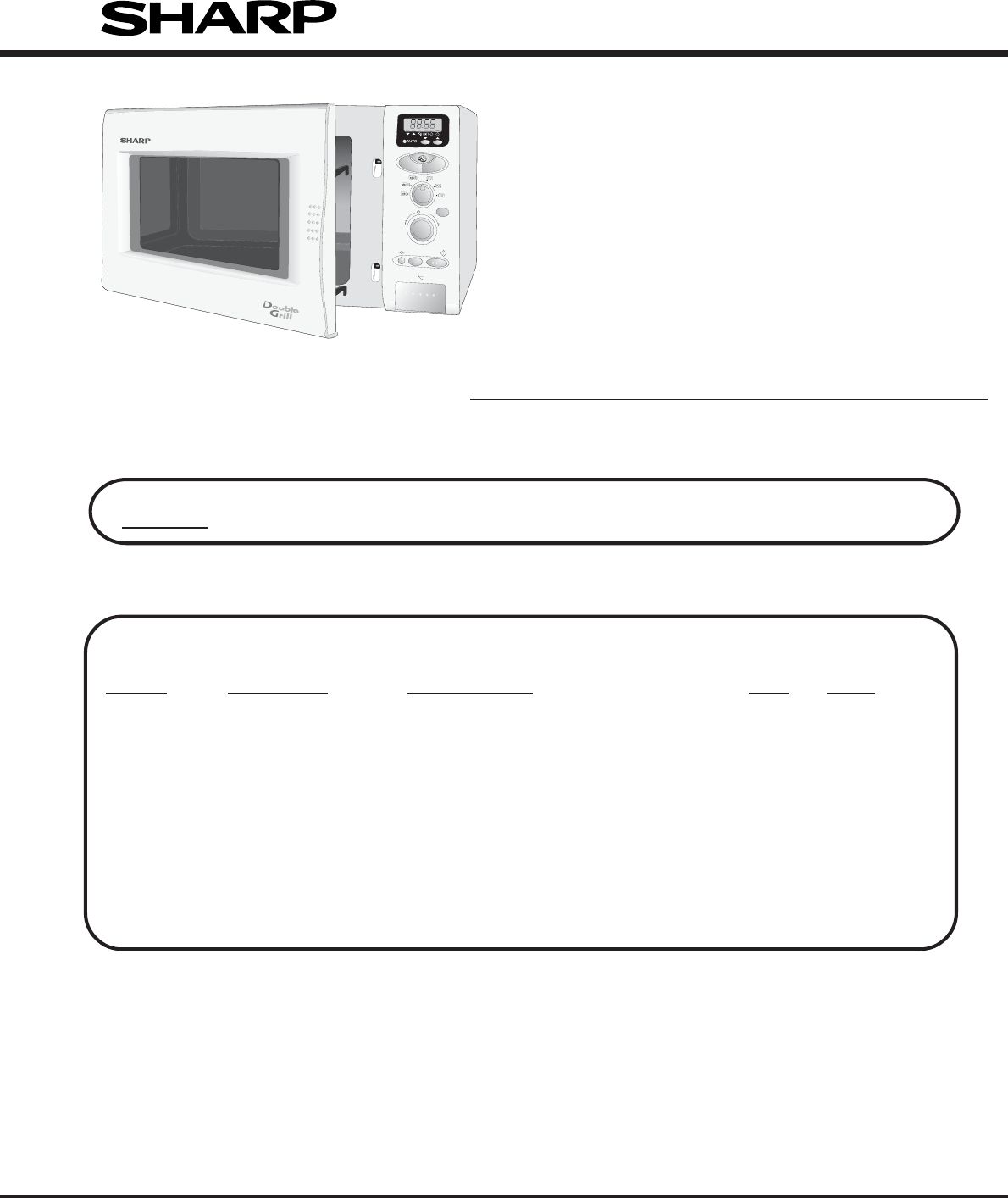
- R- 671 (W) F 1
- R-671 - 2 3
- SERVICE MANUAL 4
- SERVICING CONT 6
- PRODUCT DESCRIPTION 8
- APPEARANCE VIEW 9
- OPERATION SEQUENCE 10
- OPERATION SEQUENCE CONT 11
- TROUBLESHOOTING GUIDE 13
- TROUBLESHOOTING GUIDE CONT 14
- TEST PROCEDURES 15
- TEST PROCEDURES CONT 16
- DESCRIPTION OF LSI 21
- CONTROL PANEL ASSEMBLY 21
- DESCRIPTION OF LSI CONT 22
- SERVICING 24
- WARNING FOR WIRING 25
- TURNTABLE MOTOR REPLACEMENT 26
- OVEN LAMP REMOVAL 27
- POSITIVE LOCK 27
- CONNECTOR REMOVAL 27
- FAN MOTOR REPLACEMENT 27
- POWER SUPPLY CORD REPLACEMENT 28
- TOP HEATING ELEMENT REMOVAL 28
- DOOR REPLACEMENT 29
- R-671 - 29 30
- MICROWAVE MEASUREMENT 31
- TEST DATA AT A GLANCE 32
- CIRCUIT DIAGRAMS 33
- R-671 - 33 34
- R-671 - 34 35
- R-671 - 35 36
- IZA909DR 37
- M38223M4 37
- CIRCUIT DIAGRAMS CONT 38
- PARTS LIST 39
- PARTS LIST CONT 40
- LX-CZS030WRE0 (Ref. # 7-10) 42
- CONTROL PANEL/DOOR PARTS 43
- PACKING AND ACCESSORIES 44
- MISCELLANEOUS 44
- R-671 - 44 45
Resumo do Conteúdo
TABLE OF CONTENTSREF No PART CODE DESCRIPTION QTY CODE3-2 HPNLCW076
R-671 - 9OPERATION SEQUENCEOFF CONDITIONClosing the door activates the primary latch switch and thestop switch.IMPORTANT:When the oven door is close
R-671 - 10TOP GRILL MODEIn this mode, the food is cooked by the grill heatingelement (top grill). Select the TOP GRILL mode with theCOOKING MODE sel
R-671 - 11PIZZA COOKINGPIZZA automatically works out the correct cooking modeand time for cooking. Chose menu with the PIZZA buttonand enter the wei
R-671 - 12SPECIAL FUSE F1 15AIf the wire harness or electrical components are short-circuited, this fuse F1 blows to prevent an electric shock offir
R-671 - 13TROUBLESHOOTING GUIDE CONT...CONDITIONPROBLEMMAGNETRONHIGH VOLTAGE TRANSFORMERH.V. RECTIFIERHIGH VOLTAGE CAPACITORPRIMARY LATCH SWIT
R-671 - 14A MAGNETRON TESTPROCEDURELETTERCOMPONENT TESTCARRY OUT 3D CHECKS.Isolate the magnetron from high voltage circuit by removing all leads con
R-671 - 15PROCEDURELETTERTEST PROCEDURES CONT...COMPONENT TESTInitial temperature ...
R-671 - 16PROCEDURELETTERCOMPONENT TESTD. A short-circuited capacitor shows continuity all the time.E. An open capacitor constantly shows a resistan
R-671 - 17PROCEDURELETTERCOMPONENT TESTIf the fuse F8A (F2) is blown by incorrect door switching replace the defective switch(es) and the fuseF8A
R-671 - 18PROCEDURELETTERCOMPONENT TESTThe touch control panel consists of circuits including semiconductors such as LSI, ICs, etc. Therefore,unlike
R-671 - 1TABLE OF CONTENTSPageCAUTION, MICROWAVE RADIATION...
R-671 - 19PROCEDURELETTERCOMPONENT TESTTo protect the electronic circuits, this model is provided with a fine foil pattern added to the primary onth
R-671 - 20LSI(IZA909DR)The I/O signal of the LSI(IZA909DR) are detailed in the following table.Pin No. Signal I/O Description1-2 VL2-VL1 IN Power so
R-671 - 2112 P56 OUT Oven lamp and turntable motor driving signal(Square Waveform : 50Hz).To turn on and off shut-off relay (RY1).The square wavefor
R-671 - 2227 RESET IN Auto clear terminal.Signal is input to reset the LSI to the initial state when power is applied. Temporarilyset to "L&quo
R-671 - 231. Precautions for Handling Electronic ComponentsThis unit uses CMOS LSI in the integral part of thecircuits. When handling these parts, t
R-671 - 246. Discharge the H.V. capacitor before carrying out anyfurther work.7. Do not operate the oven with the outer case removed.N.B.; Step 1, 2
R-671 - 25HIGH VOLTAGE TRANSFORMER REMOVAL1. CARRY OUT 3D CHECKS.2. Disconnect the filament leads of high voltage trans-former from high voltage cap
R-671 - 26REMOVAL1. CARRY OUT 3D CHECKS.2. Disconnect the wire leads from the fan motor.3. Remove the two (2) screws holding the fan motor to thepow
R-671 - 27Removal1. CARRY OUT 3D CHECKS.2. Remove the one (1) screw holding the green/yellowwire to the power angle.3. Disconnect the leads of the p
R-671 - 28If the primary latch switch, stop switch and monitor switchdo not operate properly due to a mis-adjustment, thefollowing adjustment shoul
R-671 - 2CAUTIONMICROWAVE RADIATIONPersonnel should not be exposed to the microwave energy which may radiate from themagnetron or other microwave ge
R-671 - 295. Catch two (2) pins of door panel on two (2) hole of upperand lower oven hinges.6. Re-install choke cover to door panel by pushing.Note
R-671 - 30MICROWAVE MEASUREMENTAfter adjustment of door latch switches, monitor switchand door are completed individually or collectively, thefollow
R-671 - 31TEST DATA AT A GLANCEPARTS SYMBOL VALUE / DATASpecial fuse F1 15A / 250VFuse F2 F 8AThermal cut-out (HVT) TC1 145°C Off / 115˚C OnThermal
R-671 - 32Note:AC CORD CONNECTIONBRN : BROWNBLU : BLUEG-Y : GREEN AND YELLOW STRIPE/15 : SECTIONAL AREA OF 1.5mm2 MIN." " Indicates compon
R-671 - 33Figure O-3(b) Oven Schematic-Grill cooking Condition (BOTTOM GRILL mode)Figure O-2 Oven Schematic-Microwave cooking ConditionFigure O-3(a)
R-671 - 34Figure O-4(b) Oven Schematic-Dual cooking Condition (Microwave and Bottom Grill mode)SCHEMATICNOTE: CONDITION OF OVEN1. DOOR CLOSED.2. TOP
R-671 - 35Figure S-1. Pictrorial DiagramCIRCUIT DIAGRAMS CONT...BLUWHTYLWWHTBRNTC2:THERMAL CUT-OUT(OVEN)TC1:THERMAL CUT-OUT(HVT)OL: OVEN LAMP
R-671 - 36Figure S-2. Control Panel Circuit+–+–+–+–A 1LD1T1CN-ACN-CWH-B14abcd86Back LightD1D1-411ES1Q42SB1238Q40DTA143ESQ2DTA143ESQ20 DTA143ESQ2
R-671 - 37Figure S-3. Printed Wiring BoardLD5R51DCUTSW6SW4SW92423222120C51R50R53R52SW1SW7VR11ABC23C50WH - BSW8SW5( KEY AND JOG UNIT )LD5R51DCUTSW6SW
R-671 - 38CONTROL PANEL PARTS3- 1 DPWBFB840WRK0 U Control unit 1 BL3- 1A QCNCMA453DRE0 U 5-pin connector (CN-A) 1 AC3- 1B QCNCMA414DRE0 U 2-pin conn
R-671 - 3WARNINGNever operate the oven until the following points are ensured.(A) The door is tightly closed.(B) The door brackets and hinges are no
R-671 - 39∆∆∆∆CONTROL PANEL PARTS CONT...REF. NO. PART NO. § DESCRIPTION Q'TY CODER1-2 VRS-B13AA511J U Resistor 510 ohm 1W 2 ABR4-5 VRD
R-671 - 40OVEN PARTS CONT...REF. NO. PART NO. § DESCRIPTION Q'TY CODE4-12 LANGQA007URP0 U Air duct angle 1 AG4-13 LANGQA008URP0 U Grill heater
R-671 - 41OVEN PARTSNOTE:In the event of removing the turntablemotor cover, this part should be refit-ted using screw connection:LX-CZS030WRE0 (Ref.
R-671 - 42DOOR PARTSCONTROL PANEL PARTSCONTROL PANEL/DOOR PARTS4-275-75-85-85-85-85-35-45-55-15-25-63-93-73-103-43-33-133-113-123-63-23-53-83-14x 63
R-671 - 43PACKING AND ACCESSORIESTURNTABLE TRAYRACKPRINTED MATTERACCESSORY HOLDER(SPADPA010URE0)TOP PAD ASSEMBLY(FPADBA008URK0)BOTTOM PAD ASSEMBLY
R-671 - 44®'98 SHARP CORP. (7S1.31E) Printed in U.K.
R-671 - 4REMEMBER TO CHECK 3D1) Disconnect the supply.2) Door opened, and wedged open.3) Discharge high voltage capacitor.WARNING: AGAINST THE CHARG
R-671 - 5E Los hornos de microondas contienen circuitos eléctricos capaces de producir voltajes de alta tensión y descargaseléctricas. Para evitar e
R-671 - 6II forni a microonde contengono un circuito elettrico in grado di generare tensioni e correnti estremamente elevate.L’eventuale contatto co
R-671 - 7SPECIFICATIONITEM DESCRIPTIONPower Requirements 230 Volts50 HertzSingle phase, 3 wire earthedPower Consumption Microwave cooking 1.3 kW Ap
R-671 - 8OVEN9. Door seals and sealing surfaces10.Ventilation openings11.Outer cabinet12.Power supply cord13.Turntable14.Rack1. Control panel2. Oven
Mais documentos para Micro-ondas Sharp R-671

Manuais e produtos relacionados com Micro-ondas Sharp R-671

 (24 páginas)
(26 páginas)
(24 páginas)
(56 páginas)
(33 páginas)
(16 páginas)
(24 páginas)
(24 páginas)
(26 páginas)
(24 páginas)
(56 páginas)
(33 páginas)
(16 páginas)
(24 páginas)


 (32 páginas)
(22 páginas)
(21 páginas)
(28 páginas)
(32 páginas)
(28 páginas)
(68 páginas)
(21 páginas)
(54 páginas)
(32 páginas)
(22 páginas)
(21 páginas)
(28 páginas)
(32 páginas)
(28 páginas)
(68 páginas)
(21 páginas)
(54 páginas)
 (17 páginas)
(20 páginas)
(92 páginas)
(28 páginas)
(17 páginas)
(20 páginas)
(92 páginas)
(28 páginas)
© 2020, manymanuals-pt.com. Todos os direitos reservados. | 0.085 s |
 Manymanuals.com
 Manymanuals.de
 Manymanuals.fr
 Manymanuals.it
 Manymanuals.pl
 Manymanuals.cz
 Manymanuals.es
 Manymanuals-pt.com
Comentários a estes Manuais