SF-7320
SF-7370
Tv~es of test commands and their functions
- , ~ - —- --—- ------.-—..—— —.
Test command
Function
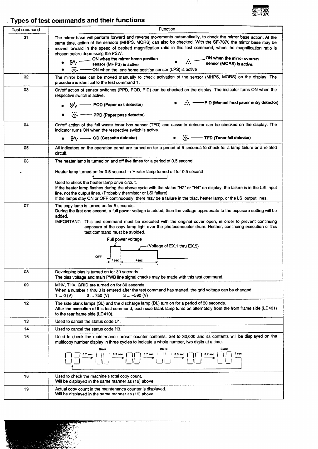
01
The mirrorbase will pedorm fo~ard and reverse movementsautomati~lYt to check tie mimerbase action. At the
same time, actionof the sensom (MHpS, MORS) can also be check~. ~~ the SF-7370 the mirrorbase may be
moved forwardin the speed of desired magnificationratio in tiis test ~mmand, when the magnificationratio is
chosenbeforedepressingthe PSW.
~ ON when the mirrorhomepoekbn
~, —ON when the
mirroroverrun
. 8+
●
sensor (MHPS) is adke.
. . .
senam (MORS) is astke.
. . .
●
%“
— ON when tie lens home positionsensor(LPS) isactive
02
me mirrorbase can be moved manually to check activationof the sensor (MHPS, MORS) on the display. The
procedureis identicalto the test command 1.
03
Otiotf actionof sensorswitches(PPD, POD, PID) can be checked on the display.The indicatorturnsON when the
respectiveswitchis active.
● 8%—
POD (Paper exti d-or)
● ●*O —
. . .
PID (Manuel feed paper em detester)
. . .
●
=.
— PPD (Paper pass detector)
04 Otioff action of tie full waste toner box sensor ~FD) and cassette detector can be checked on the display. The
indicatorturnsON whenthe respectiveswitchisactive.
● 8+ —
CD (Cassette detester)
. . .
●
=.
— TFD ~oner fuUdetector)
05 All indicatorson tie operationpanel are turnedon for a period of 5 seconds to check for a lamp failureor a related
circuit.
06
The heater lamp is turnedon and off five times fora periodof 0.5 second.
Heater lampturnedon for 0.5 second+ Heater lampturnedofffor 0.5 second
t I
Used to checkthe heater lamp drivecircuit.
If the heater lamp flashes duringthe above cycletith the status“H2. or .H4” on display,the failureis in the LSI input
line, notthe outputlines. (Probablythermistoror LSI failure).
If the lampsstay ON or OFF continuously,there may be a failurein the triac, heater lamp, or the LSI outputlines.
07 The copy lamp is turnedon for 5 seconds.
Duringthe firstone second, a fullpower voltageis added, then the voltage appropriateto the ex~sure settingwillbe
added.
IMPORTANT: ~is test command must be executed with the original cover open, in order to prevent continuing
exposure of the copy lamp lightover the photoconductordrum. Neither, continuingexecutionof this
test commandmustbe avoided.
Fullpowervoltage
~ (Voltageof EX.1 thruEX.5)
0-
1
4W
::
*
08 Developingbiasis turnedon for 30 seconds.
The bias voltageand main PWB line signalchecksmaybe made with this test commend.
09 MHV, THV, GRID are turnedon for 30 seconds.
When a number1 thm 3 is entered after the test commandhas started,the gridvoltagecan be changed.
1 ...0 m 2,..750 (w 3... +90 (w
12
The side blanklamps (SL) and the dischargelamp (DL) turnon for a periodof 30 seconds.
Afterthe executionof thistest command, each side blank lamp turnson dtemately from the frontframe side (LD401)
to the rear tiame side (LD41O).
13
Usedto cancelthe statuscode U1.
14
Used to cancel the statuscode H3.
16
Used to check the maintenance preset counter contents. Set to 3 0 ,0 0 0 and its contents will be displayed on the
multicopynumberdisplayin three cyclesto indicatea wholenumber,two digitsat a time.
Bb*
Bk*
B hk
——
l—l :1 ~ / // / ~ 1–1 1-1 ~ I / / / ~ I –JI –I ~ / / / / ‘ *
——
——
ill
1–1 1–1 – – – – –.
I I I I
I I I I I I 1–1
——
——
f
18
Used to checkthe machine’stotalc opy count.
VVillbe displayedin the same manneras (16) above.
19
Actualcopycountin the maintenancecounteris displayed.
Will be displayedin the same manner as (16) above.
.-—— -.-.-—

 (36 páginas)
 (10 páginas)
 Manymanuals.com
 Manymanuals.de
 Manymanuals.fr
 Manymanuals.it
 Manymanuals.pl
 Manymanuals.cz
 Manymanuals.es
 Manymanuals-pt.com
Comentários a estes Manuais