Sharp R-480J Manual de Serviço
Consulte online ou descarregue Manual de Serviço para Micro-ondas Sharp R-480J. Sharp R-480J Service manual [en] Manual do Utilizador
- Página / 40
- Índice
- MARCADORES
- SERVICE MANUAL 1
- SERVICE MANUAL 3
- PRODUCT SPECIFICATIONS 4
- GENERAL INFORMATION 4
- APPEARANCE VIEW 5
- OPERATION SEQUENCE 6
- POWER OUTPUT REDUCTION 7
- SERVICING 9
- POSSIBLE CAUSE 10
- DEFECTIVE PARTS 10
- TEST PROCEDURE 10
- HIGH VOLTAGE RECTIFIER 12
- is approx. 20˚C) 13
- QKITPB026MRE0 16
- COMPONENT TEST 17
- TEST PROCEDURES 17
- PROCEDURE 17
- TOUCH CONTROL PANEL ASSEMBLY 18
- 20.0 msec 19
- During cooking 19
- SEG67-SEG40 21
- Sensing part 22
- (Open vessel) 22
- (Closed vessel) 22
- Thermistors 22
- TOUCH CONTROL PANEL SERVICING 23
- WARNING FOR WIRING 24
- MAGNETRON REMOVAL 25
- TURNTABLE MOTOR REMOVAL 25
- POSITIVE LOCK 25
- COOLING FAN MOTOR REMOVAL 26
- Noise filter 27
- Power supply cord 27
- Brown wire 27
- Blue wire 27
- Green/Yellow wire 27
- DOOR REPLACEMENT 28
- Sealer film 29
- Backing film 29
- Adhesive tape 29
- MICROWAVE MEASUREMENT 30
- 230-240V/50Hz 31
- HIGH VOLTAGE COMPONENTS 32
- Figure S3. CPU. Unit Circuit 34
- PARTS LIST 36
- Not replaceable items 37
- INTO THE 37
- OVEN CAVITY 37
- OVEN AND CABINET PARTS 38
- CONTROL PANEL PARTS 39
- DOOR PARTS 39
- MISCELLANEOUS 39
Resumo do Conteúdo
R-480JTABLE OF CONTENTSPageCAUTION, MICROWAVE RADIATION ...
R-480J8CK = Check / RE = ReplaceHome fuse blows when power supply cord is plugged into wall outlet.FUSE F10A blows when power supply cord is plugged i
R-480J9TEST PROCEDURESPROCEDURELETTERCOMPONENT TESTA MAGNETRON TESTNEVER TOUCH ANY PART IN THE CIRCUIT WITH YOUR HAND OR AN INSULATED TOOLWHILE THE OV
R-480J10D HIGH VOLTAGE CAPACITOR TESTTEST PROCEDURESPROCEDURELETTERCOMPONENT TESTRoom temperature ... To = 21˚C Initial temperature ...
R-480J11TEST PROCEDURESPROCEDURELETTERCOMPONENT TESTB. Continuity check must be carried out with measuring instrument which is set to the highest resi
R-480J12K TOUCH CONTROL PANEL ASSEMBLY TESTTEST PROCEDURESPROCEDURELETTERCOMPONENT TESTH MOTOR WINDING TESTCARRY OUT 3D CHECKS.Disconnect the leads fr
R-480J13TEST PROCEDURESPROCEDURELETTERCOMPONENT TESTb) At a certain digit, brightness is low.c) Only one indicator does not light.d) The corresponding
R-480J14TEST PROCEDURESPROCEDURELETTERCOMPONENT TESTChecking the initial sensor cooking conditionWARNING : The oven should be fully assembled before f
R-480J15TEST PROCEDURESPROCEDURELETTERCOMPONENT TESTTESTING METHOD FOR AH SENSOR AND/OR CONTROL UNITTo determine if the sensor is defective, the simpl
R-480J16TOUCH CONTROL PANEL ASSEMBLYOUTLINE OF TOUCH CONTROL PANELThe touch control section consists of the following units.(1) Key Unit(2) Control Un
R-480J17LSIThe I/O signal of the LSI is detailed in the following table.Pin No. Signal I/O Description1 COM5 OUT Common data signal : COM11. Connected
R-480J1837 P05 OUTKey strobe signal.Signal applied to touch-key section. A pulse signal is input to AIN7, P14, P15, P16 and P17terminal while one of G
R-480J19Pin No. Signal I/O Description63-66 AIN3-AIN0 INTerminal to change cooking input according to the Model.By using the A/D converter contained i
R-480J20SW1SW2SW3SW4SW5P20P21P22P23P24 LSI(IC1)AIN4AIN5620k300k150k75k37.4k2623225049242515k15k4.7k123487650.01uF0.1uF0.01uFVA : -15VVA : -15VR90330C9
R-480J211. Precautions for Handling Electronic ComponentsThis unit uses CMOS LSI in the integral part of thecircuits. When handling these parts, the f
R-480J22COMPONENT REPLACEMENT AND ADJUSTMENT PROCEDUREWARNING:Avoid possible exposure to microwave energy. Please follow the instructions below before
R-480J23Removal1. CARRY OUT 3D CHECKS.2. Disconnect wire leads from magnetron.3. Remove the two (2) screws holding the magnetron airduct to magnetron.
R-480J24OVEN LAMP AND LAMP SOCKET REMOVAL1. CARRY OUT 3D CHECKS.2. Remove one (1) screw holding the chassis support tothe magnetron and magnetron air
R-480J252. Install the fan motor to the back plate of the oven cavitywith the two (2) screws.3. Re-install the fan duct to the oven cavity.4. Connect
R-480J26toward the oven face. Then check lower portion of thelatch hook, pushing and pulling lower portion of thedoor toward the oven face. Both resul
R-480J27door panel upward.5. Hold the door panel to the door frame with three (3)screws.6. Re-install the latch spring to the latch head. Re-installth
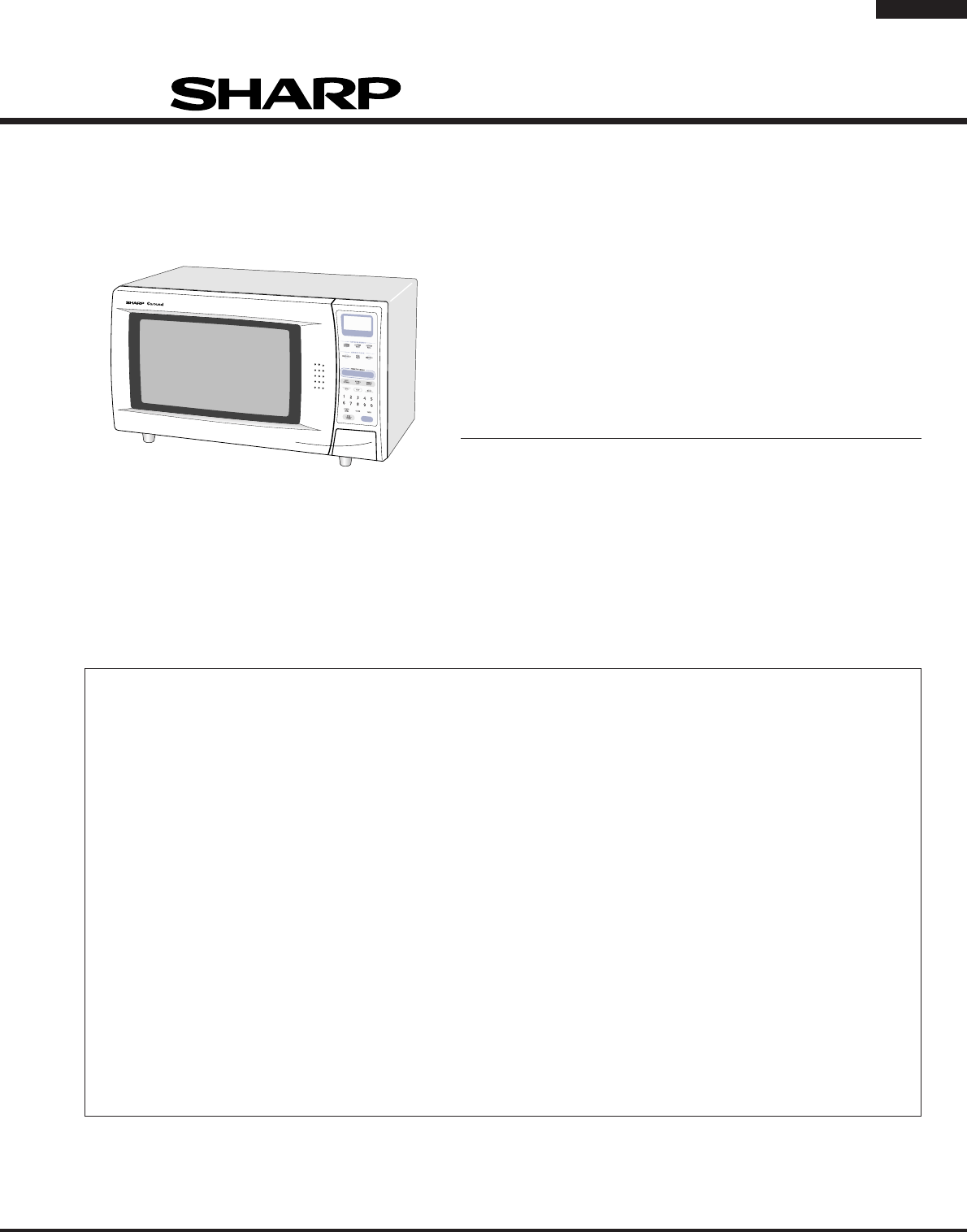
R-480J1SERVICE MANUALMICROWAVE OVENR-480JGENERAL IMPORTANT INFORMATIONThis Manual has been prepared to provide Sharp Corp. Serviceengineers with Opera
R-480J28MICROWAVE MEASUREMENTAfter adjustment of door latch switches, monitor switchand door are completed individually or collectively, thefollowing
R-480J29SCHEMATICNOTE: CONDITION OF OVEN1.DOOR CLOSED.2.CLOCK APPEARS ON DISPLAY.NOTE: " " indicates components with potentials above 250V.F
R-480J30Figure S-1. Pictorial Diagram1ABCDEFGHABCDEFGH23456123456COM.MONITORSWITCHCOM.N.O.N.C.2ND. INTERLOCKRELAY CONTROLSWITCH1ST. LATCHSWITCHTURNTAB
R-480J31Figure S-2. Power unitl Circuit1ABCDEFGHABCDEFGH23456123456+–+–+–A 1B 2 B 1CN-AR4 27D5T1abcdVRS1(J1)D7D81SS270A1SS270A10G471KC1 0.1µ/50vC3 0.1
R-480J32Figure S3. CPU. Unit Circuit1ABCDEFGHABCDEFGH23456123456SENSOR DEFROST TURNTABLE OFF COOKHELPC11+-0.1uF/50V(J17) (J16)(J15) (J14)(J13)(J12)(J1
R-480J331ABCDEFGHABCDEFGH23456123456Figure S-4. Printed Wiring BoardWH - 1SH - BSH - A1C3C4C5R3C2FC110D4D2D1D3D9(D10)RY3(CN - D)D8ZD1VRBDUR2R1 R6 R5SP
R-480J34∆∆PARTS LISTNote: The parts marked "∆" may cause undue microwave exposure.The parts marked "*" are used in voltage more th
R-480J35HOW TO ORDER REPLACEMENT PARTSTo have your order filled prompty and correctly, please furnish the following information.1. MODEL NUMBER2. REF.
R-480J361ABCDEFGHABCDEFGH23456123456OVEN AND CABINET PARTS7-87-87-87-82-16-71-54-54-207-14-117-17-47-14-67-61-157-24-91-137-54-14-71-94-41-31-41-31-14
R-480J371ABCDEFGHABCDEFGH23456123456CONTROL PANEL PARTSDOOR PARTSActual wire harness may be different from illustration.6-24-185-45-85-85-55-65-15-75-
R-480J2PRODUCT SPECIFICATIONSITEM DESCRIPTIONPower Requirements 230 - 240 Volts50 HertzSingle phase, 3 wire earthedPower Consumption 1.65 kWPower Outp
R-480J'04SHARP CORP. (08S0.CD_E)COPYRIGHT © 2004 BY SHARP CORPORATIONALL RIGHTS RESERVED.No part of this publication may be reproduced, stored in
R-480J3APPEARANCE VIEW1. Ventilation openings2. Oven lamp3. Door hinges4. Door safety latches5. See through door6. Door seals and sealingsurfaces7. Co
R-480J4OPERATION SEQUENCEbecause the relay (RY1) stays closed. Shown in thedisplay is the remaining time.6. MONITOR SWITCH CIRCUITThe monitor switch i
R-480J52. Heat potatoes. Moisture and humidity is emitted rapidly.You can smell the aroma as it cooks.3. Sensor detects moisture and humidity and calc
R-480J6Figure D-1. Door Open Mechanism1ST. LATCH SWITCH AND 2ND. INTERLOCK RE-LAY CONTROL SWITCH1. When the oven door is closed, the contacts (COM-NO)
R-480J7SERVICINGMicrowave ovens contain circuitry capable of pro-ducing very high voltage and current, contact withany part of the high voltage circui
Mais documentos para Micro-ondas Sharp R-480J


Manuais e produtos relacionados com Micro-ondas Sharp R-480J
 (16 páginas)
(88 páginas)
(16 páginas)
(88 páginas)
 (10 páginas)
(20 páginas)
(16 páginas)
(24 páginas)
(24 páginas)
(40 páginas)
(16 páginas)
(21 páginas)
(59 páginas)
(25 páginas)
(2 páginas)
(10 páginas)
(20 páginas)
(16 páginas)
(24 páginas)
(24 páginas)
(40 páginas)
(16 páginas)
(21 páginas)
(59 páginas)
(25 páginas)
(2 páginas)
 (48 páginas)
(31 páginas)
(24 páginas)
(71 páginas)
(42 páginas)
(1 páginas)
(48 páginas)
(31 páginas)
(24 páginas)
(71 páginas)
(42 páginas)
(1 páginas)
© 2020, manymanuals-pt.com. Todos os direitos reservados. | 0.042 s |
 Manymanuals.com
 Manymanuals.de
 Manymanuals.fr
 Manymanuals.it
 Manymanuals.pl
 Manymanuals.cz
 Manymanuals.es
 Manymanuals-pt.com
Comentários a estes Manuais