Sharp 32UC4 Manual de Serviço
Consulte online ou descarregue Manual de Serviço para TVs e monitores Sharp 32UC4. Sharp 32UC4 Service manual Manual do Utilizador
- Página / 40
- Índice
- MARCADORES
- SERVICE MANUAL 1
- SAFETY NOTICE 3
- (Continued) 3
- BEFORE RETURNING THE RECEIVER 3
- (Fire & Shock Hazard) 3
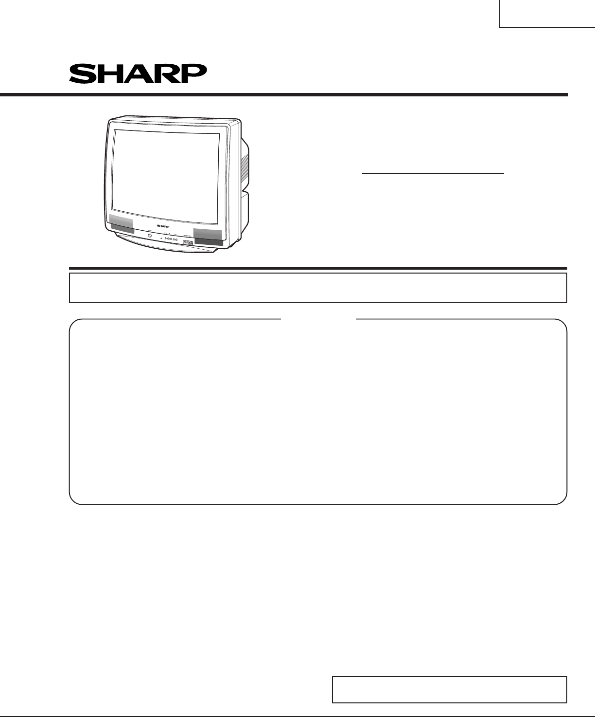
- Front Panel 4
- CIRCUIT PROTECTION 5
- HIGH VOLTAGE CHECK 5
- A. VCJ IC ADJUSTMENT 7
- E. PIP IC ADJUSTMENT 8
- B. SPECIAL SETTING 8
- C. OPTION SETTING 8
- D. SOUND ADJUSTMENT 8
- B-AMP Base waveform in step 10
- MTS ADJUSTMENT 11
- P-IN-P ADJUSTMENT 12
- WAVEFORMS 13
- CHASSIS LAYOUT 14
- BLOCK DIAGRAM 15
- SCHEMATIC DIAGRAM: CRT Unit 17
- 1716 1918151413121110 19
- PWB-B: CRT Unit (Wiring Side) 28
- PARTS LIST 30
- PWB-A: DUNTKB567WEV8 31
- PWB-A: DUNTKB567WE8 32
- PWB-A: DUNTKB567W8 34
- PWB-B: DUNTKB568WEV1 35
- PWB-D: DUNTKB572WEV0 36
- PWB-R: DUNTKA533WEA3 36
- MISCELLANEOUS PARTS 38
- SUPPLIED ACCESSORIES 38
- PACKING PARTS 38
- CABINET PARTS 38
- CABINET PARTS LOCATION 38
- PACKING OF THE SET 39
Resumo do Conteúdo
32UC4SHARP CORPORATIONThis document has been published to be used for aftersales service only.The contents are subject to change without notice.In the
1032UC4SERVICE ADJUSTMENTRF AGC Adjustment1. Receive a good local channel.2. Enter the service mode and select the serviceadjustment "R01".3
1132UC4C. C Display Position Adjustment1. Receive the lion head pattern signal.2. Select "EX2" to display the text box.3. Adjust the "E
1232UC4ËP-IN-P ADJUSTMENTP-IN-P Y-LEVEL Adjustment1. Receive a good local channel.2. Enter the service mode and select the serviceadjustment "P0
1332UC4WAVEFORMS
1432UC4CHASSIS LAYOUT
1532UC4BLOCK DIAGRAM
1632UC4DESCRIPTION OF SCHEMATIC DIAGRAMNOTES:1. The unit of resistance "ohm" is omitted.(K=kΩ=1000Ω, M=MΩ)2. All resistors are 1/16 watt,
1732UC4654321ABCDEFGHSCHEMATIC DIAGRAM: CRT Unit
87109654321AB CDEFGH1832UC4SCHEMATIC DIAGRAM: MAIN-1 Unit25
1716 19181514131211101932UC4
232UC4IMPORTANT SERVICE SAFETY PRECAUTIONËService work should be performed only by qualified service technicians who arethoroughly familiar with all s
87109654321AB CDEFGH2032UC4SCHEMATIC DIAGRAM: MAIN-2 Unit
1716 19181514131211102132UC4
87109654321AB CDEFGH2232UC4SCHEMATIC DIAGRAM: 2 LINE Y/C Unit
1716 19181514131211102332UC4
87109654321AB CDEFGH2432UC4SCHEMATIC DIAGRAM: P-IN-P Unit
1716 19181514131211102532UC4
2632UC4654321ABCDEFGHPWB-A: MAIN Unit (Components Side)PRINTED WIRING BOARD ASSEMBLIES
2732UC4654321ABCDEFGHPWB-A: MAIN Unit (Chip Parts Side)
2832UC4654321ABCDEFGHPWB-B: CRT Unit (Wiring Side)PWB-D: 2 LINE Y/C Unit (Chip Parts Side)PWB-D: 2 LINE Y/C Unit (Wiring Side)
2932UC4654321ABCDEFGHPWB-R: P-IN-P Unit (Wiring Side)PWB-R: P-IN-P Unit (Chip Parts Side)
332UC4SAFETY NOTICEMany electrical and mechanical parts in televisionreceivers have special safety-related characteristics.These characteristics are o
Ref. No. Part No. ★ Description Code Ref. No. Part No. ★ Description Code3032UC4PICTURE TUBE★ MARK: SPARE PARTS-DELIVERY SECTION' MARK: X-RAY
Ref. No. Part No. ★ Description Code Ref. No. Part No. ★ Description Code3132UC4PWB-A: DUNTKB567WEV8MAIN UNIT(Continued)D510 RH-DX0441CEZZ∗ X DX0441CE
Ref. No. Part No. ★ Description Code Ref. No. Part No. ★ Description Code3232UC4PWB-A: DUNTKB567WE8MAIN UNIT(Continued)C607 VCKYPA1HB472K+ X 4700p 50V
Ref. No. Part No. ★ Description Code Ref. No. Part No. ★ Description Code3332UC4PWB-A: DUNTKB567WEV8MAIN UNIT(Continued)RESISTORSRJ1 VRS-CY1JF000J∗ X
Ref. No. Part No. ★ Description Code Ref. No. Part No. ★ Description Code3432UC4PWB-A: DUNTKB567W8MAIN UNIT(Continued)å R710 VRS-RG2HC103J+ X 10k 1/2W
Ref. No. Part No. ★ Description Code Ref. No. Part No. ★ Description Code3532UC4PWB-A: DUNTKB567WEV8MAIN UNIT(Continued)R2404 VRD-RA2BE101J∗ X 100 1/8
Ref. No. Part No. ★ Description Code Ref. No. Part No. ★ Description Code3632UC4PWB-B: DUNTKB568WEV1CRT UNIT(Continued)R876 VRD-RA2BE121J∗ X 120 1/8W
Ref. No. Part No. ★ Description Code Ref. No. Part No. ★ Description Code3732UC4PWB-R: DUNTKA533WEA3P-IN-P UNIT(Continued)C1803 VCKYCY1HB103K∗ X 0.01
Ref. No. Part No. ★ Description Code Ref. No. Part No. ★ Description Code3832UC4MISCELLANEOUS PARTSSUPPLIED ACCESSORIESPACKING PARTS (NOT REPL
3932UC4PACKING OF THE SET★ Packing Case★ MARK : Not replacement items.FRONT★Buffer Material★ Polyethylene Mat★ Polyethylene BagOperation ManualInfrare
432UC4LOCATION OF USER'S CONTROLFront PanelCHANNEL UP/DOWN( ) Selects next higher channel.( ) Selects next lower channel.VIDEO/AUDIO TE
4032UC4COPYRIGHT © 2003 BY SHARP CORPORATIONALL RIGHTS RESERVED.No part of this publication may be reproduced,stored in a retrieval system, or transmi
532UC4CIRCUIT PROTECTIONThe receiver is protected by a 4.0A fuse (F701),mounted on PWB-A, wired into one side of the ACline input.X-RADIATION PROTECTO
632UC4Figure A.V012CHANNELSERVICE ADJUSTMENT NUMBERDATA NUMBERFor adjustments of this model, the bus data is converted to various analog signals by th
732UC4SERVICE NUMBERDATAADJUSTMENT ITEMINITIAL VALUERANGENOTEV01 PICTURE 0-15 (00h-0Fh) 8 (08h)V02 TINT 0-127 (00h-7Fh) 66 (42h)V03 COLOR 0-127 (00h-7
832UC4SERVICE NUMBERDATAADJUSTMENT ITEMINITIAL VALUERANGEP01 CONTRAST-PIP 0-127 (00h-7Fh) 73 (49h)P02 TINT-PIP 0-63 (00h-3Fh) 41 (29h) 29P03 COLOR-SAT
932UC4NECESSARY UNNECESSARYADJUSTMENTPART REPLACEDIC2001IC201XData is stored in IC2101.The adjustment is needed to compensate for characteristics of p
Manuais e produtos relacionados com TVs e monitores Sharp 32UC4
 (34 páginas)
(64 páginas)
(14 páginas)
(39 páginas)
(64 páginas)
(30 páginas)
(46 páginas)
(110 páginas)
(60 páginas)
(22 páginas)
(34 páginas)
(64 páginas)
(14 páginas)
(39 páginas)
(64 páginas)
(30 páginas)
(46 páginas)
(110 páginas)
(60 páginas)
(22 páginas)
© 2020, manymanuals-pt.com. Todos os direitos reservados. | 0.090 s |
 Manymanuals.com
 Manymanuals.de
 Manymanuals.fr
 Manymanuals.it
 Manymanuals.pl
 Manymanuals.cz
 Manymanuals.es
 Manymanuals-pt.com
Comentários a estes Manuais