Sharp R-408J Manual de Reparação
Consulte online ou descarregue Manual de Reparação para Micro-ondas Sharp R-408J. Sharp R-408J Repair manual Manual do Utilizador
- Página / 28
- Índice
- MARCADORES
Resumo do Conteúdo
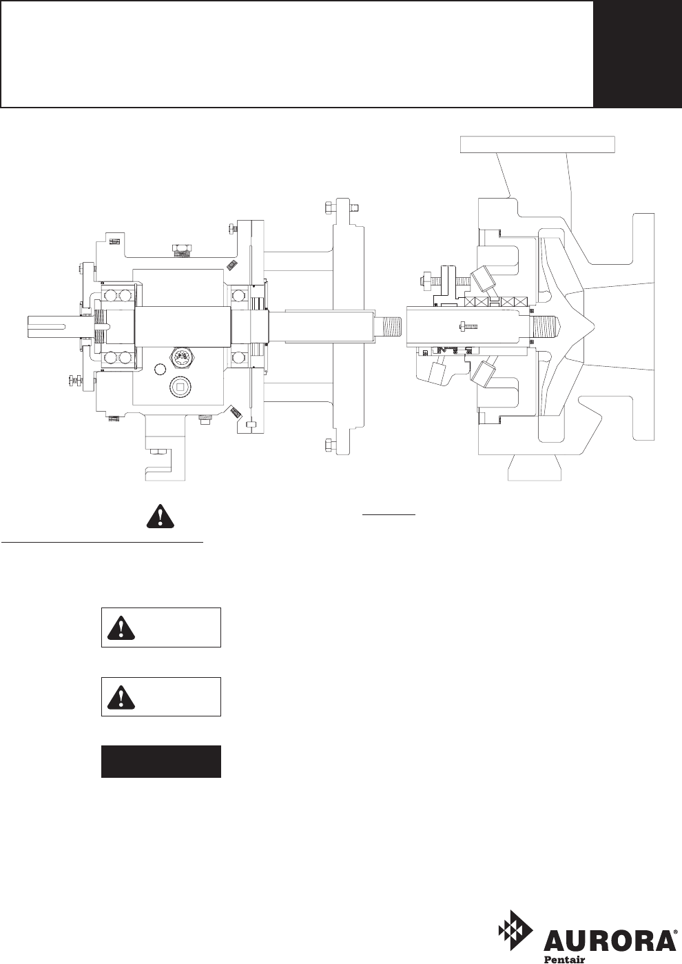
INSTRUCTION, INSTALLATION, MAINTENANCE AND REPAIR MANUAL3500 SERIES / MODEL 3550 ASME/ANSI B73.1MFRAMES S, M, L AND XL – INDUSTRIAL PROCESS PUMPS2SECT
3500 SERIES / MODEL 355010 Tag valves as standard practice.MAINTENANCE:DISASSEMBLY: Always use a lifting device capable of supporting the full weigh
3500 SERIES / MODEL 355011 8. Use frame adapter (108) or frame (228) for placing hoisting strap. 9. Remove bearing frame foot hold-down bolts and cas
3500 SERIES / MODEL 355012FRAME ADAPTER REMOVAL – M, L, XL:Remove the following components in the order listed below: •Dowelpins(469B)andbolts(
3500 SERIES / MODEL 355013 •Localizedwearorgroovinggreaterthan1/8"(3.2mm)deep •Pittinggreaterthan1/8"(3.2mm)deep •Check
3500 SERIES / MODEL 355014 8. Install new O-ring (496). 9. Use oil to coat the outside of outboard bearing (112) and bearing housing (134) bore. 10.
3500 SERIES / MODEL 355015 NOTE: Consult Appendix V (page 24) for detailed labyrinth seal installation instructions. NOTE: Keyway edges must be fr
3500 SERIES / MODEL 355016 2. Check shaft end play by moving shaft forward and backward by hand, taking note of indicator movement. If total indicator
3500 SERIES / MODEL 355017FOR OUTSIDE MOUNTED SEALS: 11. Install the mechanical seal on shaft (122) or, if applicable, sleeve (126) following the seal
3500 SERIES / MODEL 355018Fault Possible Cause RemedyExcessive shaft end play. Bearing internal clearance too great.•Reducespeedlevel.Snap ring lo
3500 SERIES / MODEL 355019S – PUMP CROSS SECTIONAL 100184101412250370H357K360Q351105106107353355503370126333408H168228113408H112134370C3821363324001
3500 SERIES / MODEL 35502PUMP DESCRIPTION:Fill this in for your record purposes: It will be critical to have this information for the accurate identi
3500 SERIES / MODEL 355020L – PUMP CROSS SECTIONAL 100184101412351105106107353355126250370H357K360Q370108333360D370B408H228113408H 253B236A370C134382
3500 SERIES / MODEL 355021PARTS & MATERIAL COMPOSITIONItem NumberReq’d Per Pump Part NameAllSteelAll316SSAllAlloy 20All CD4MCuAllTitaniumHastelloy
3500 SERIES / MODEL 355022APPENDIX I: IMPELLER CLEARANCE ADJUSTMENT:FEELER GAUGE METHOD: 1. Lock out power supply to motor. 2. Remove coupling guard
3500 SERIES / MODEL 355023 3. Once coupling guard half (pump end) is located around end plate, tighten it securely with a bolt, nut and two washers t
3500 SERIES / MODEL 355024APPENDIX IV Bolt Torque, ft.-lbs. (Nm)Location Frame All Materials, All ModelsLube DryCasing Bolts (370) orCasing Nuts (425)
3500 SERIES / MODEL 355025APPENDIX VI: PRESSURE – TEMPERATURE RATINGS:–400 –300 –200 –100 0 100 200 300 400 500 600–240 –200 –160 –120 –
3500 SERIES / MODEL 355026APPENDIX VII: PARTS INTERCHANGEABILITY CHART:Impellers and casings are different for each pump size. Stuffing box covers and
3500 SERIES / MODEL 355027WARRANTY:Seller warrants equipment (and its component parts) of its own manufacture against defects in materials and workman
3500 SERIES / MODEL 355028Aurora Pump800 Airport RoadNorth Aurora, IL 60542phone: 630-859-7000fax: 630-859-7060NOTE:Aurora Pump reserves the right to
3500 SERIES / MODEL 35503MAINTENANCE SAFETY DATA:Warning: Toxic Fluid HandlingHazardous or toxic fluids must be flushed and properly disposed of befor
3500 SERIES / MODEL 35504INTRODUCTION:RECEIVING SHIPMENT: Upon receiving shipment, check items against packing list. Be sure to inspect entire box fo
3500 SERIES / MODEL 35505LEVELING: Acceptable parallel machined bearing plates or chock blocks need to be placed under the base along the sides and e
3500 SERIES / MODEL 35506Excess forces and moments on the pump may occur due to: •Thermalexpansionandcontractionofthepipingindicatingimprope
3500 SERIES / MODEL 35507ORIENTATION: •For suction above centerline: Eccentric – Flat side onbottom. Concentric. •For suction below
3500 SERIES / MODEL 35508Change oil every 12 months. Oil should be changed more frequently under severe environmental conditions (dust, moisture, corr
3500 SERIES / MODEL 35509 a. When making adjustments, unseat the mechanical seal from the shaft. b. Check total clearance. Confirm that it follows t
Mais documentos para Micro-ondas Sharp R-408J

Manuais e produtos relacionados com Micro-ondas Sharp R-408J
 (20 páginas)
(36 páginas)
(32 páginas)
(56 páginas)
(32 páginas)
(42 páginas)
(36 páginas)
(20 páginas)
(36 páginas)
(32 páginas)
(56 páginas)
(32 páginas)
(42 páginas)
(36 páginas)
 (87 páginas)
(24 páginas)
(12 páginas)
(63 páginas)
(43 páginas)
(32 páginas)
(100 páginas)
(133 páginas)
(71 páginas)
(50 páginas)
(87 páginas)
(24 páginas)
(12 páginas)
(63 páginas)
(43 páginas)
(32 páginas)
(100 páginas)
(133 páginas)
(71 páginas)
(50 páginas)

 (92 páginas)
(53 páginas)
(59 páginas)
(92 páginas)
(53 páginas)
(59 páginas)
© 2020, manymanuals-pt.com. Todos os direitos reservados. | 0.043 s |
 Manymanuals.com
 Manymanuals.de
 Manymanuals.fr
 Manymanuals.it
 Manymanuals.pl
 Manymanuals.cz
 Manymanuals.es
 Manymanuals-pt.com
Comentários a estes Manuais